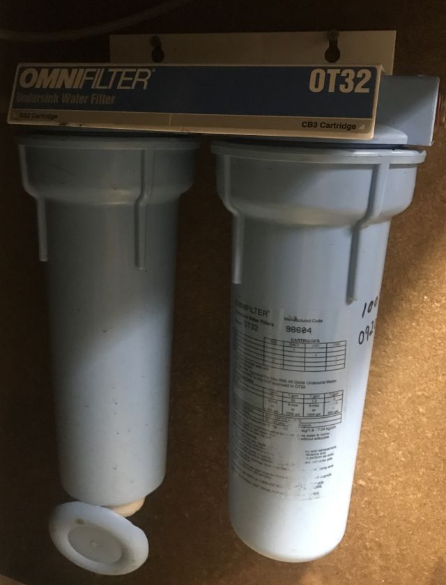
In July 1998 I installed an undersink filter. I know the date because I kept the original installation instructions. I remember the accompanying written warning but paid little attention: “To prevent costly repairs or possible water damage we strongly recommend that the housing be replaced periodically: every five years for clear tanks, and every ten years for opaque tanks. If your housing has been in use for more than the recommended period, it should be replaced immediately”.
Imagine my surprise and dismay in November 2016 when, upon returning to the house, we noticed water in the garage coming from the entrance way which leads to the kitchen, and the kitchen and most of the dining room floors covered with water. Yup, as the above picture shows, the bottom of one of the housings had separated and its failure produced a mini flood.
Busy I was with a commercial carpet cleaner vacuuming up the water on a non stop basis for several hours. Then with fans and the heaters to dry the carpets. Over the next 24 hours we were reasonably successful, except for the entrance where the underlay and the concrete floor were so wet they stayed damp and began to smell. I lifted the carpet and underlay/pad and continued heating the area until the foundation had dried. Then installed a new underlay and re-installed the carpet. So normalcy returned and we were fortunate we had carpet and tile rather than wood floors.
My communications with the manufacturers made little headway. The new housings they carried would not fit the old base so they could not offer a goodwill replacement. And they courteously reminded me of the warning to replace the housing within 10 years of installation. I could not argue.
I bought a new undersink filter with just a single cartridge. We had previously needed a 2 cartridge system but with sediment no longer an issue, a high quality chlorine eliminator filter was all that was needed. And the water bill for that month showed unusual usage of close to 1,000 gallons. So, if you have an undersink filter, remember to replace the housings timely.
Much time since my last post. My uncovered greens have held up well through the cold and I have begun germinating tomato seeds. Read some excellent books and took a MOOC on software design in connection with 3D printing. And I have spent considerable time diagnosing and fixing my silent Takeuchi TL26 (bobcat).
I don’t use it much but the compost heap needed turning and I wished to grade some ground for additional rainwater tanks, and it stayed silent when I turned the key. Not good.
Previously I had looked at the electrical system diagram (wiring diagram) but did not really understand it. It is one thing to wire components together or replace components (see my posts on replacing failed capacitors), but it is a different ball game actually understanding what’s going on when you turn the key. So this time I resolved to understand how the electrics for starting the bobcat actually work and to step by step test each link and find out what was wrong.
I write up the whole experience separately on this website – if interested please follow this link
The testing process was a slog in part because of poor testing procedures. Here I will mention the problem I had testing the battery.
Warning – a friend, who is a former eye surgeon, told me he had many patients whose eyes were damaged by battery acid. He said an exploding battery is a nasty thing and I should always wear eye protection and keep water nearby for washing off acid.
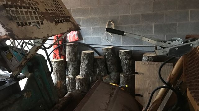
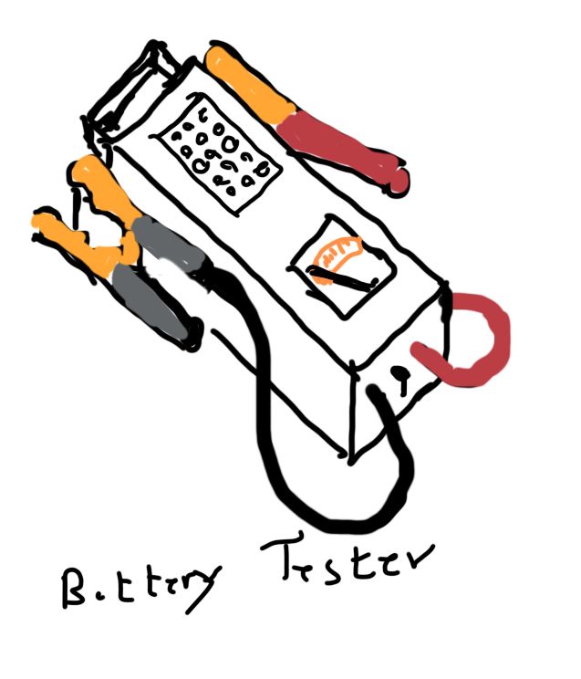
When I pulled the cab forward over the bucket (actually I winched it forward – see photo above), I noticed the negative terminal/post was badly sulphated (covered in white guck). Apparently a sulphated negative terminal can indicate undercharging by the alternator, and a sulphated positive terminal overcharging – just something I read, don’t quote me. I was not surprised since I suspected the alternator was not charging properly and had previously resolved to test it, but never got around to it. I cleaned the ground terminal and charged the battery for a couple of hours. This is a relatively new battery purchased in second half of 2014. Then I decided to test it with Schumacher battery load tester – this is the tester with the big battery clamps and you hold the switch toggle on for 10 seconds and it applies a load and you can tell the real condition of the battery.
my Schumacher BT-100
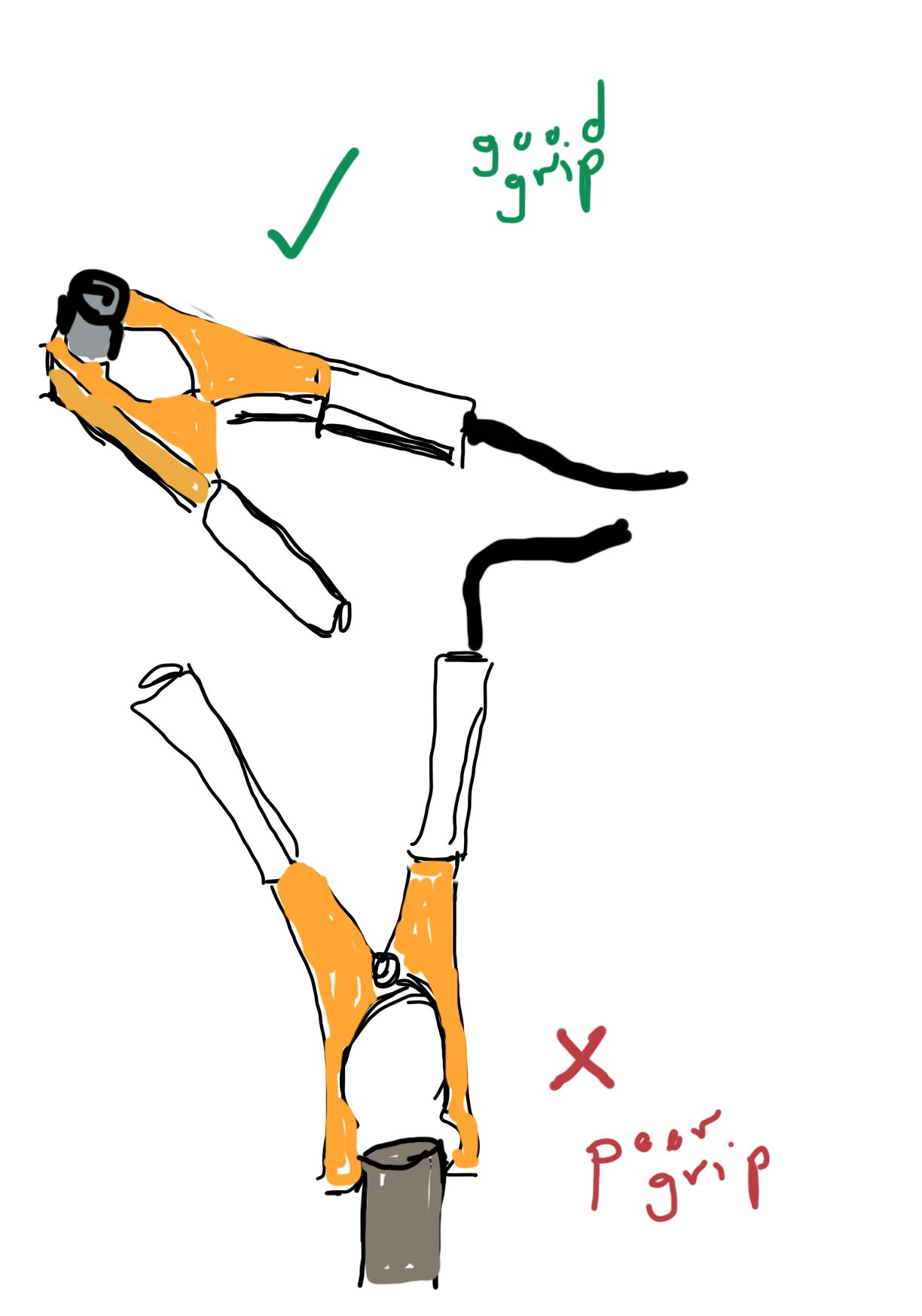
The tester showed 12+ volts before I applied the load and nothing when I applied the load. I was surprised and hauled the battery out of the bobcat (pulled it forward between the lip of the bobcat and the raised cab, which is easier than climbing into the engine area and lifting vertically) and took it indoors and charged it with a sophisticated charger. After 1 hour it said the battery was fine. I tested with Schumacher with 10 second load and it was fine. Took it back to the bobcat connected the terminal clamps, and no response from engine. Decided on a hunch to test again with the Schumacher – nothing. How was this possible? Removed the terminal clamps and applied the Schumacher clamps directly to the battery terminals – read fine. So either the terminal clamps were not making good contact with the battery posts or the Schumacher clamps were not making good contact with the battery terminal clamps. I cleaned the terminals and terminal clamps, reconnected and applied the Schumacher clamps. Tested fine. I removed the Schumacher clamps and then reapplied them – nothing. But now I was concentrating and there was a fizzing/spritzy sound from the Schumacher clamps and the terminal clamps. So this was a problem solved – to get a good load test I had to make sure the Schumacher clamps are tightly seated before applying the load.
8 clamp teeth gripping are better than 4 teeth
A long description of a faulty testing procedure. But I learned. In the link to my detailed testing you can read how I took several wrong turns as a result of faulty testing procedures.
I should mention that an internet authority recommended 3 battery tests – 1) voltage >12.6v; 2) battery load test (described above); 3) use an electronic battery tester. So I purchased a Solar Battery Tester (model BA5) and followed the procedures including inputting the battery CCA of 925. The tester said the battery was fine and calculated the CCA at 830, which should be more than sufficient to start the engine. I would have been surprised if the battery had failed since, to my mind, if the battery passes the load test it should be ok for starting the engine. With 2 testers both indicating the battery was fine, I ruled out the possibility of a bad battery.
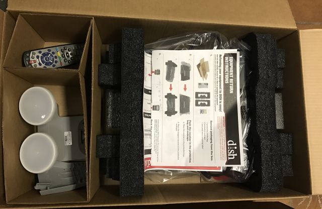
It all began when the tv satellite bill for the Atlanta house jumped unexpectedly. The company explained I was beyond the 6 month special discount period and offered to split the difference between old rate and new rate. I decided to become a “cord-cutter” and canceled the contract. They sent me a shipping box and I disconnected the LNB from the satellite dish and placed it and the receiver and remote in the box and bade farewell at the UPS office.
“Now what?” M. demanded to know. She did not watch shows or movies but was hooked on Classic Arts Showcase (“CAS”).
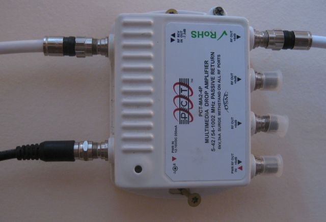
I decided to switch to a mix of antenna tv and internet tv. For the antenna I followed lessons learned while installing an antenna in the log cabin (see my Sept 6, 2016 post) and with a 16dB amplifier at the mast was able to access > 30 stations, none of which appealed to M.
For internet tv, after briefly considering the Google and Apple options, I plumbed for Roku. Roku does not have a recorder as did my satellite service but I can access previous output so a recorder is not critical. I discovered Pluto which consolidates a number of stations and it has “The Opera Network” but M. was not appeased. Met. Opera on demand was interesting to her but not the same. Then I discovered Qello channel for concert films and music documentaries, and peace appeared to return for a monthly cost of $7.95. But then I was told Qello was not as nice as CAS. CAS is broadcast but my antenna could not access the broadcast channels. I found I could access CAS via laptop and watch on tv via hdmi cord. M. thought this was cumbersome. I then discovered CAS is available on Nowhere TV which is available as a Roku private channel with input of a special code. Peace is restored.
Roku made obvious that our Earthlink dsl 6mbps speed was inadequate for simultaneous video watching and computer use. After lengthy calls with ATT and Earthlink I again decided to support the little guy (as I did with the Roku decision) and signed up for the Earthlink hyperlink connection which now provides download speeds of 18 mbps to 24 mbps – great. The ATT installer (although the contract is with Earthlink the service is provided by ATT) explained that if our house was closer to the fiber optic connection point the speed would be much faster (at least double) but we are towards the end of a long copper run. By eliminating some unnecessary POTS services, the additional cost for hyperlink is minimal.
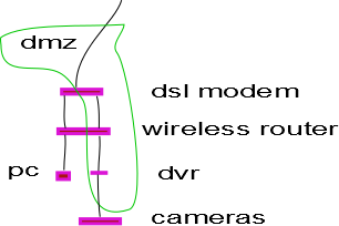
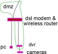
Instead of a separate dsl modem and wireless router, the 2 are combined and this simplifies accessing my cameras remotely. The modem and router both act as firewalls and both had to be programmed to permit external access to the dvr (digital video recorder) which controls my cameras.
with a dmz (demilitarized zone) the modem and router no longer bar external access to the dvr
Now with dsl and router combined only one device has to be programmed.
of course there is a risk that with firewall removed my cameras may be hijacked & so I have to use strong passwords
And finally, after saving some by fixing a water well problem and by eliminating monthly satellite bill, I splurged and upgraded my iPhone 4 to an iPhone 7. The iPhone 4 works fine for calls, texting and email. However, several important apps such as the app for remotely viewing my house cameras now require IOS 8 or higher and iPhone 4 does not support IOS 8. Reluctantly I decided, it was time for a change and I am enjoying all the upgraded apps not previously accessible and a very good camera.
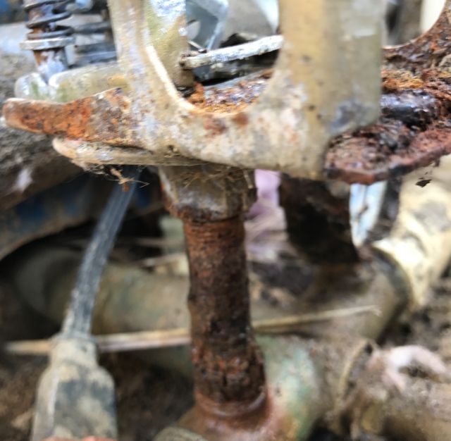
In my previous post (part 1) I describe the temporary repair I made to the expansion tank pressure switch. However the pipe/nipple connecting the pressure switch to the water manifold is badly rusted and seeping water and just a matter of time before it disintegrates.
I want the repair to proceed efficiently and so I researched how to removed broken nipples – Bob’s plumbing video (how to remove a broken pipe) was very helpful. So prior to commencing the repair I bought and assembled all the tools and parts I would need – new pressure gauge; new pressure switch set for range 30psi to 50psi; 4″ long 0.25″ diameter brass pipe; an extractor kit for broken pipes; assortment of brushes to clean threads; rust penetrant oil; and my usual assortment of standby tools. And then off to the well head.
Caution – following involves working with 240 volts and can result in serious injury or death and should not be undertaken by anyone not competent in this area.
I first switched off the power, then removed dome and pressure switch cover and photographed the wires so I could remember later which were connected to which. With a tire gauge I measured the air pressure in the expansion tank – it was 45psi. I opened a faucet and drained the water from the expansion tank. Then I looked at the nipple and, as previously mentioned, it was in bad shape.
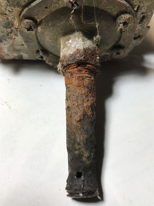
with the switch disassembled you can see the extent of rusting of switch and nipple
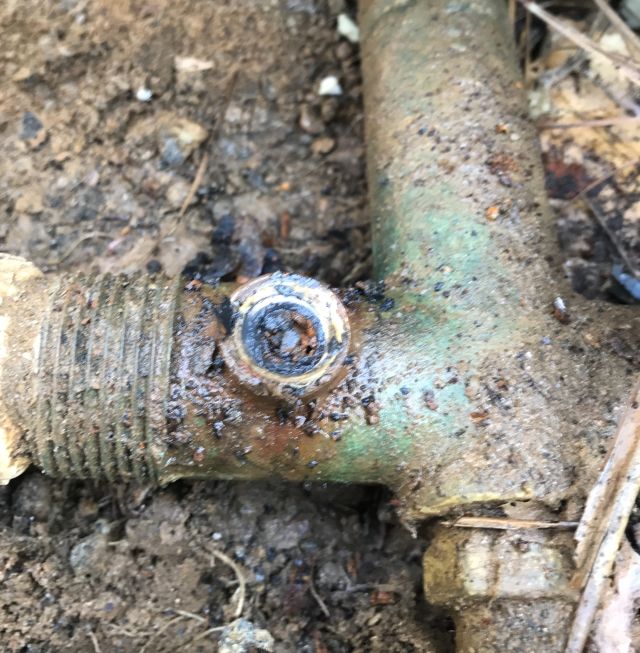
After dowsing with rust penetrating oil I tried gently undoing the nipple from manifold and it turned for a bit and then broke away leaving some pipe in the hole.
some rusted pipe remaining in whole after unscrewing the nippleyou can see the rust and small water hole and little bit of thread which unscrewed
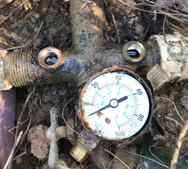
With my nipple extractor the rest of the pipe in the hole appeared to disintegrate and I then cleaned the female threads with brass brushes. While I was at it I also removed the broken water gauge.
the 2 cleaned holes – 1 for the nipple, 1 for the gauge, and the old gauge
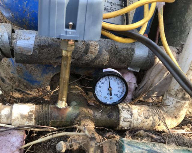
And installed a new gauge and was disconcerted to see that somehow I had cracked the glass cover. I used pipe thread sealant and connected up the new pressure switch and pressure gauge.
the new parts in place and the expansion tank charged. I will try replace the cracked glass cover of the gauge
And then switched on the power and watched the gauge rise to 50psi and heard the switch click open and stop the pump. Everything was working fine. I checked the expansion tank pressure with my tire gauge and it was 45psi. Mission accomplished.
Unexpectedly, Friday evening, no water in the house. No warning signs such as discolored water which could indicate the well was running dry. Checked the power supply board and the switch was on. Called the well repair guy and asked if any wells were running dry. He said 12 in the mountains but none at my level and he would visit Saturday 6pm.
Caution – following involves working with 240 volts and can result in serious injury or death and should not be undertaken by anyone not competent in this area.
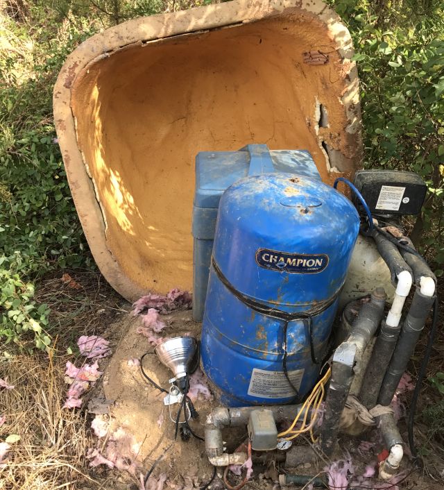
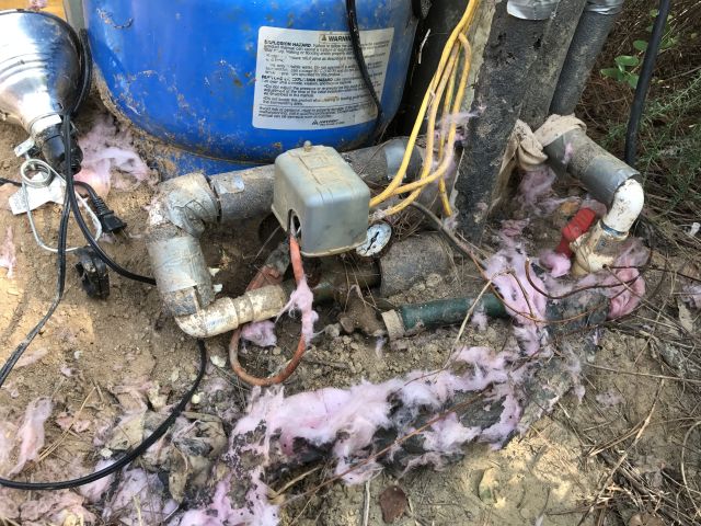
the grey box in the middle is the pressure switch for the blue expansion tank
Saturday morning I lifted the dome cover over the wellhead and removed the cover over the wires.
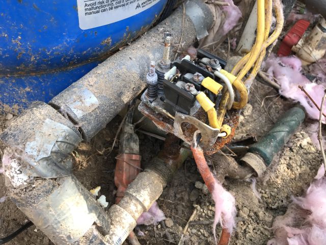
with cover removed wires carrying 240 volts are exposed
Yes, the wires from the house were carrying 240 volts. I then switched off the power. So what could be the problem? The well is about 400 feet deep and that’s where the pump is located. The problem could be a break in wires to pump, pump itself, water pipe from pump to surface or from wellhead to house, or worst case, a dry well. The the pump was pulled and replaced in 2007 – cost $1,200. Pumps usually last longer but ground lightning strikes can prematurely age a pump. My neighbors well ran dry a few years ago and to drill, fracture and install a new well cost around $12,000. The potential costs could be high.
The ground from wellhead to house was rock solid dry which is what you get in the extreme drought situation in north Georgia – so no leak between wellhead and house. While I was at it I walked over the septic tank and pipeline area and it was dry, so no ongoing leak in the house draining the well.
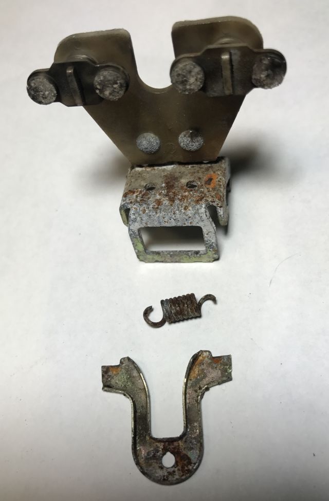
Back to the wellhead. Could there be another issue? The expansion tank for this well is located at the wellhead. The function of the expansion tank is to extend the life of the pump by holding reserve water under pressure for the house and when the water pressure in the tank falls below a set level it then switches on the pump. Typically it switches on the pump when the pressure falls to 30 psi and switches off the pump when the pressure reaches 50psi. Thus the life of the pump is extended since it does not have to cycle on and off every time water is used in the house. The expansion tank is connected to a pressure switch which is normally in the closed (on) position and it opens (cuts power off) when the expansion tank is fully charged. I looked more closely at the switch and noticed the plate which should be closed when water is needed was loose and not touching and providing continuity to the terminals (if you look carefully you will see there is no contact between the plate and the terminals).
There is a spring which holds the plate to the terminals and it must have broken and was not in sight. It seemed there were 2 ways forward – replace the entire switch or just the spring. The small pipe called a nipple, which connects the switch to the main pipe is badly corroded and I am quite sure will not come undone without disintegrating.
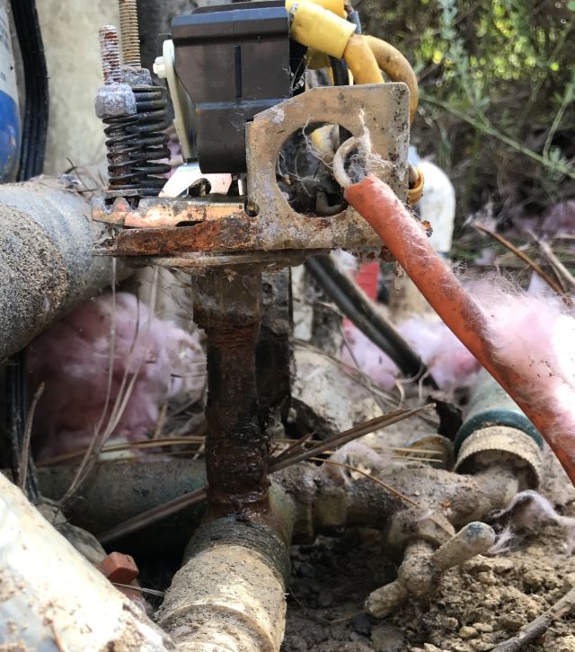
corroded pipe which joins pressure switch to water manifold. not only badly rusted but also leaking water
I wanted a quicker fix for the time being and decided to try replacing the spring. Fortunately I have a spare previously used switch and so I headed to my workroom and, after brewing a fresh mug of coffee, began dismantling the spare switch to figure out how to access the spring which is below several other parts, and how to re-assemble it. First attempt took about 20 mins, second attempt 10 mins, and by 4th attempt I could do it from any angle in about 5 mins. I removed the spring and some adjacent parts from the spare switch and headed back to the wellhead. And about 10 mins later the switch was repaired and I switched back on the power and the house received water and, as expected, once the expansion tank was charged, the switch snapped open.
you can see the old spring which failed (right clasp broken) & 2 other parts which I replaced as well
So the switch appears to work ok and I canceled the visit from the well repair guy, and I am now thinking how I will remove and replace the corroded pipe. See part 2.
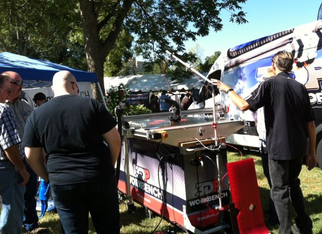
There is a Maker movement afoot and a few weeks ago I visited my first Maker Faire, which was in Atlanta. A few weeks prior I signed up for a MOOC (online course) on 3D printing and I was deciding which 3D printer I should buy – the large one in the photo above costs around $30k, I was thinking of $300. Makers enjoy tinkering and making things most often using new technologies. I think this is different from DIY where the focus is on repairing or installing things, which would usually be done by a contractor.
I enjoy understanding how things work – both natural and fabricated. So therefore my organic growing activities where I interact with a complex changing natural force. When I was 16, just for the heck of it, I separated the rear engine of my Mom’s Renault Dauphine car from the rest of the body. And hastily re-assembled it when confronted by my irate Dad. During my London years (1978-1986) I did a lot of work on an old, neglected house including installing 17 hot water radiators – see my write up referenced on “self reliance & projects list.” So I suppose I have a Maker’s instincts.
The Faire was absorbing – there were a number of 3D printer vendors who were happy to engage in discussion. I chatted to the folks at Freeside Atlanta who describe themselves as ” a community of makers, tinkerers, engineers, programmers, artists, teachers, and lunatics”. Lincoln Electric had a welding simulator which charitably graded my wobbly bead at 47%.
there were several arenas for battles between autonomous grappling machines or in this case a ball hurler(1746) which gathers up a white ball and propels it into the air
Fun was watching the drone racing competition as these screaming fast moving airborne objects chased around the course and then dived through rectangular frames at different heights.
a serious contest of technology and human reflexes
It was fun, I learned some and a week later after more research I purchased a HICTOP self assembly 3D printer for $316. I will write separately of the assembly, calibration and first print experience. If you are curious you can read my review today on Amazon.
In my recent post on September 4 I described the installation of a whole house filter, see schematic below.
pipes, fittings and the filter which I installed
Since this was the first time I was using pex, I was concerned there could be a rupture or seepage in the basement during the night when I was not at the house and so I disconnected power to the well pump which is located deep in the ground. The following day when I switched on the power I was surprised that the pump had to run for some time to charge the expansion tank. I thought there could be a leak and, yes the outside faucet was leaking. I repaired the faucet, disconnected the power that evening and the next day no water emerged from the kitchen faucet and again the well pump had to refill the expansion tank. So I visited the other outside faucet which was fine and all the faucets in the house and the washing machine connections and listened to the toilets, and all seemed fine. I gloomily concluded that the check valve in the well was leaking and the water in the expansion tank was leaking back into the well.
My searches on the internet advised that adding a second check valve just before the expansion tank was not a good idea and that I should have the pump pulled and replaced (minimum cost $1,200 if done by contractor) or there could be a leak in the line from the house to the well head or the well head to the pump. But was this really the reason?
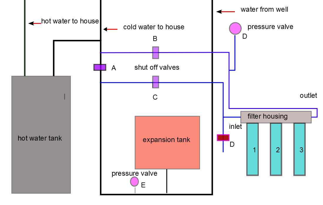
I decided to use available instruments to determine the cause. I shut off the water valve at C (the valve at A is always closed) and disconnected the power to the pump and noted the psi pressure reading at E and time of observation. I did not use any water and 50 minutes later was surprised and relieved to see the psi had not budged. So this meant that no water was leaking back to the well. I connected power to the well pump, opened C and allowed pressure to normalize and then closed C and noted pressure at D. Even as I watched, the meter at D slowly rotated to 0. So there was a leak somewhere and my valuable well water was being squandered. Again I visited all the outlets but this time, instead of listening to the toilets I removed the cover of each toilet. And in the last toilet the water was silently overflowing into the overflow tube because the float was not shutting off the fill valve. This will be a quick, easy and inexpensive repair and far, far better than having to deal with a bad well check valve. And with hindsight, the diagnostics to perform were obvious, but isn’t that always the case with hindsight?
serendipity
Common sense is important but a little luck along the way is always welcome. Yesterday at 4.30am, when I was away from the logcabin, my smart phone began chanting I had received a text and it was a “security event zone 2 alarm” at the logcabin which meant something triggered the sensor in the kitchen and my neighbors were being awakened from their slumbers. I quickly shushed the alarm and looked at the cameras and all was well and so I reset the alarm. Zone 2 has been triggered twice in the past 3 months and at the time of one of the triggerings a camera in the kitchen captured a large moth flying in the room. Was it again the moth?
This time the cameras were silent but it could still have been the moth since the camera and and the sensor are in different parts of the room. I decided to open the sensor case to lower its sensitivity and, to my surprise a small spider emerged from inside the cover of the sensor. I now think that this spider was hanging out in the sensor case and it triggered the alarm by crossing the face of the sensor. I removed the spider and some nearby webs. Hopefully this solves the zone 2 alarms. And it was serendipitous, since I was not looking in the sensor case for an inhabitant – but I will take luck anytime.
6 years ago I wanted to receive TV via antenna. We have DSL and I can access Netflix and YouTube etc. but not local stations. I positioned the antenna facing south (Atlanta’s direction) about 20 feet off the ground and connected a cable from the antenna to the cable attached to the previous owner’s dish receiver, and in the winter received a few stations. Since I have digital TV and the signal is digital I do not require a converter box. In the summer reception fell off because the trees grew leaves. I lost interest in the project. Now I have re-engaged.
some technicals
I input my street address at website “antennaweb.org” and it tells me which stations can be accessed and their direction relative to my house. Most are from Atlanta about 40 miles distance. The website “tvfool.com” provides more detailed analysis of nearby channels including the signal strength (Noise Margin decibels– NM(dB)).
I have grappled with but never understood dB (decibels) which is a measurement of the intensity of sound. It is about logarithms, a weak area for me, except that I remember that instead of multiplying two numbers you can take their logs and add them together and the antilog gives the result of multiplication. If the intensity of sound falls by half so the output is (0.5), the input, this is described as a 3 dB fall – the log calculation is 10log 0.5 i.e. take the log of 0.5 and multiply by 10 and the answer is -3.0dB. As the TV signal wends its way through the house to the TV it loses strength – if you wish to power 2 TV’s you use a splitter to split the input into 2 outputs and a consequence is the signal is reduced by half which is 3dB (usually 3.5dB is used in calculations). If 100 ft of RG-6 cable is used and the frequency carried is 700MHz, there is a further loss of 5.6dB, so total loss is 9.1dB (-3.5dB-5.6dB). If you add an amplifier at the antenna end which has a rating of +8dB, then the net loss is 1.1dB. So a nice feature using dB is you simply add up the gains and losses and ensure your signal strength is not too diminished on its way to the TV. You could also use a dB signal meter which is now offered for <$100 (used to be >$500) but not worth the investment for one time use.
I mention that signal loss in the cable is affected by the frequency carried. The impact is significant – for example the attenuation (reduction) to a 50MHz signal on 100ft RG-6 is 1.4dB and for a 900MHz signal is 6.0 dB. A 200ft cable has twice the loss, a 50ft cable half the loss. Which raises the question – what is the frequency of the stations I receive?
There are two bands VHF and UHF. VHF for the 2 stations I receive, has frequency range between 174 and 216 MHz, and the UHF frequency range is between 470 and 890 MHz. Almost all the channels I receive are UHF. So when I design my system I have to ensure it will adequately handle frequencies up to 900 MHz.
back to installation
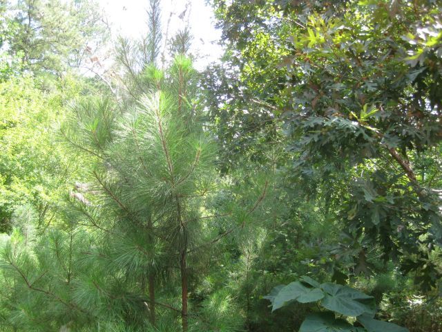
As mentioned, in summer the view of the antenna was blocked by branches and leaves, shown below:
horizontal summer view from old antenna location, 12 ft above ground level
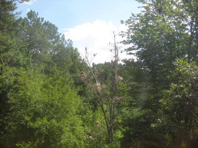
Rather than attach the antenna to the chimney (lightning hazard?) or locate in the attic (signal interference from steel roof?), I moved it to a south facing dormer window.
horizontal summer view 24 ft above ground level
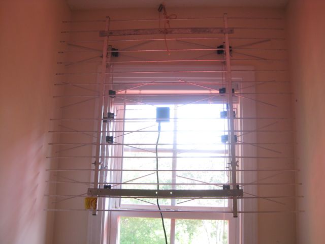
The old antenna was too wide so I snipped off a couple of inches from each side and suspended it from the ceiling.
the width reduced antenna suspended from the ceiling in the dormer window bay
Next step was to connect the antenna to the TV in the living room. I decided to use the existing RG-6 TV cables in the house since every room had been wired for TV and there was a nearby outlet. I connected a battery to the outlet and headed for the basement and located the cable which carried 9 DC volts. I did the same in the living room and then knew which 2 cables to connect.
the connected cables are middle right
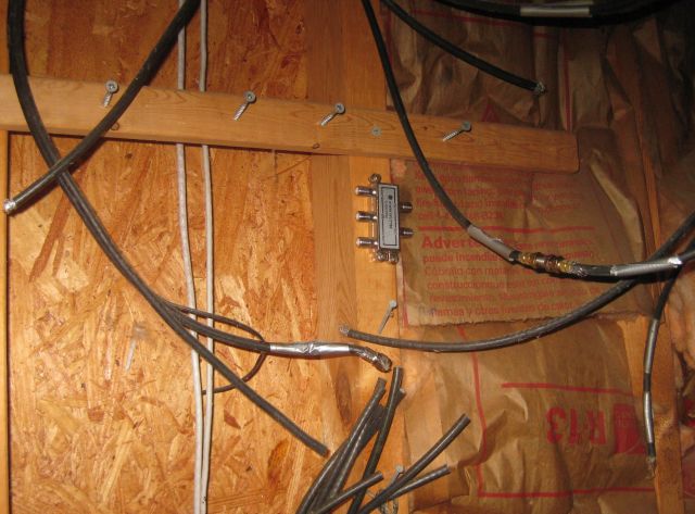
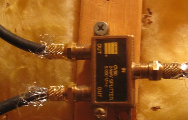
Not knowing better at the time, I used 2 splitters – 1 for connecting upstairs cables and 1 for the basement cables.
a splitter with antenna signal entering on right & 1 output to upstairs room and 1 output to basement
I instructed the TV to scan for digital channels and it found 8. I thought I could do better and decided to eliminate the 2 splitters since I was only using 1 TV in the house, and directly connect the cables together.
direct connection of the cables
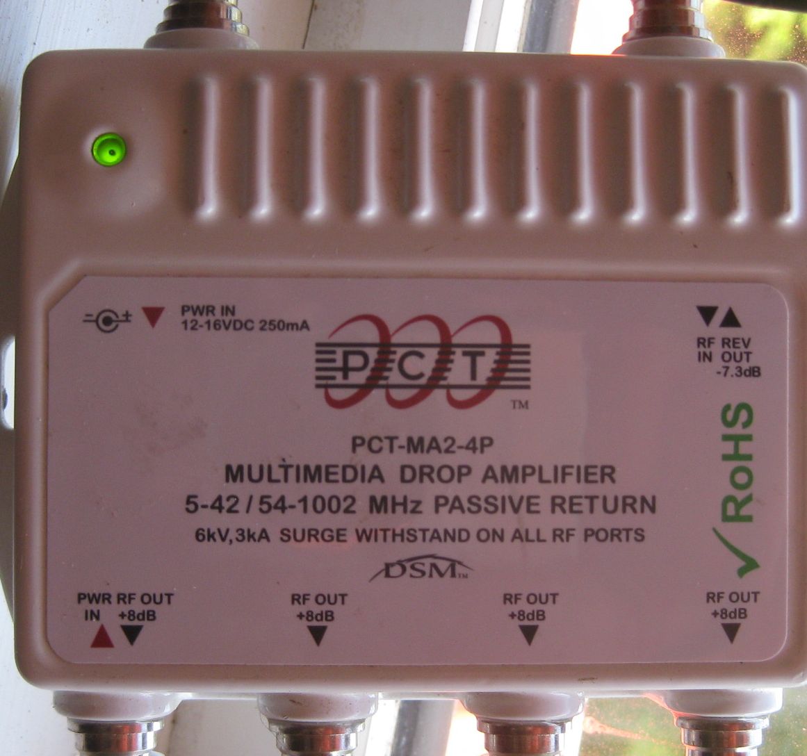
The TV now located 18 channels. I was on a roll. I remembered I had once purchased a signal amplifier so I connected it at the antenna end and the TV was now able to locate 34 digital channels.
signal amplifier, you can see it enhances the signal by 8dB
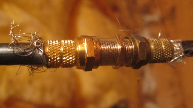
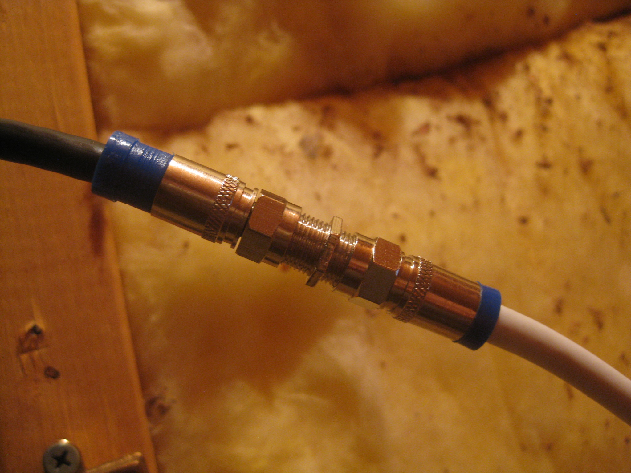
Could I do even better? This far I had incurred no cost – the screw on cable connectors, stub RG-59 cable and the signal amplifier were leftovers from previous projects. The screw on cable connector not only looks amateurish but has a practical disadvantage – you twist it clockwise onto the cable and then you twist its rotating cap clockwise onto the male thread of the TV or antenna or connector. And the 2nd twisting motion is opposite to the first and unless you are careful you can loosen the grip on the cable and weaken the connection. So I ordered for for about $20 a package containing a stripping tool to remove the sheathing on the cable, a compression crimping tool which compresses fittings on the cable, and blue locking compression connectors. For good measure I also ordered an additional 50 black connectors for about $10. I also decided to replace the RG-59 stub cables with RG-6 which is a thicker cable with better insulation for higher frequency signals and the 20 ft length of black RG-59 in the living room was conspicuous against the white walls. So I ordered 100 ft of white RG-6 for $16. I had now invested just under $50 and was hoping for better reception.
I replaced the 3 stub cables (antenna to amplifier, amplifier to upstairs room cable, living room outlet to TV) with RG-6 cable and the twist on cable connectors with the attractive blue compression connectors. Instead of 34 channels my TV now scanned 14 channels. This was a setback. I remembered the basement connectors were twist on cable and found one was loose and replaced them with blue compression connectors and I now go 18 channels. It seemed one of 3 things could be wrong – the cable was bad, the connectors were bad or my technique was bad. I reexamined all the connections and found one I had forgotten to compress.
my new blue connectors
You can see the connector on the left was not compressed, so I compressed with the compression crimp tool and the TV located 24 channels, 11 less than with the old cable and connectors. I examined the cable and it clearly stated it was RG-6 and I concluded it could not be the problem. Then I examined the blue connectors and found each had a rubber ring inside the threaded female twist cap. The ring probably protects against moisture but it could also block end on end electrical contact. Perhaps this was the problem? So I replaced 9 blue connectors with the new black compression connectors. And…
A few weeks ago M. confronted me in the kitchen with a glass of discolored water. “It’s dirty” she accused. I agreed but suggested if she wanted drinking water she should use the under sink 2 stage filters I installed, which deliver crystal clear water, and not worry about the water from the faucet. She was not appeased and said she would not shower in discolored water nor did she want the dishes or clothing to be washed in the water. We have a deep well I explained so bacteria is not an issue and there was probably a lightning strike which shook up the ground and displaced some sediment.
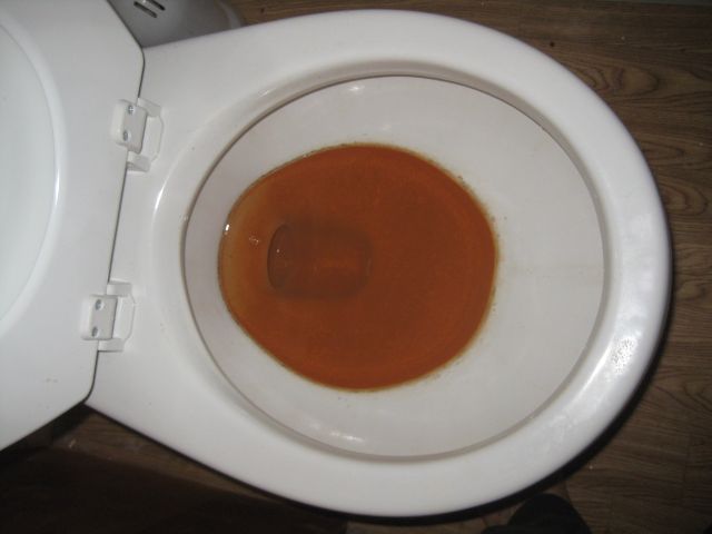
I mentioned this to my neighbor across the road and he said the discoloration was iron in the water and he used a whole house filter and replaced the cartridge every few months. Time for some research, and I found an excellent YouTube video which clarified. Iron in well water which is dissolved or in solution is called ferrous. When exposed to oxygen it precipitates and becomes visible and is called ferric. A sediment filter cannot trap ferrous but will remove ferric. So if you install a single filter where the well water enters the house it will remove ferric but the ferrous will slip by and will precipitate into ferric while sitting in the water heater or the toilet bowl. This solved a puzzle. Our house has an upstairs bathroom which is rarely used. Every few months I flush the upstairs faucets and toilet to ensure there is water in the traps. And the toilet bowl always has red/brown sediment, yet when last flushed a few months previously I had brushed the bowl clean. How did all this sediment get into the bowl? I now conclude the invisible ferrous in the water precipitated into ferric which settled in the bowl.
unappetizing sight – iron sediment precipitated in bowl
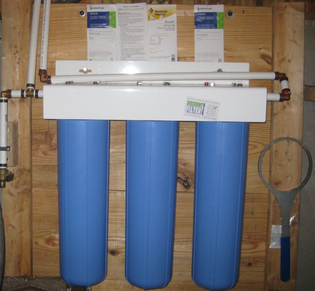
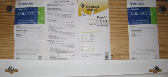
The youtube video recommended 3 filters used in series. The 1st is a sediment filter to trap any sediment and ferric in the well water so it will not clog the 2nd more expensive filter. The 2nd filter (Pentek RFFE-20BB) contains agents (apparently potassium permanganate) which oxidize the water and thereby precipitates the ferrous into ferric. The 3rd filter, like the 1st is a sediment filter which traps the ferric which was produced by the 2nd filter. Pretty neat!
details on the filters – sediment filters on each end and iron filter in middle
Typical filters are 20” in height and enclosed in big blue tubes and therefore called big blue filters. I researched prices and found I could get a better deal (>10% less on a comparable basis) from an independent rather than big A, except for one of the filters which I ordered from big A. A few days later the packages arrived.
Plumbing technicals
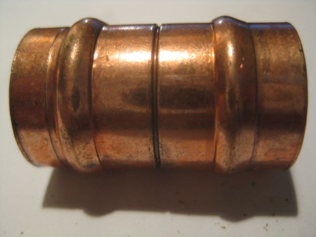
When I lived in London I completely replumbed an old house including installing a gas furnace and 17 radiators and a pump and 3 thermostat controlled motorized valves. I used copper pipe and soldered all the joints except for a few compression fittings. It was much easier to solder a joint in the U.K than in the U.S.A. because, for amateurs like me, there were the wonderful Yorkshire capillary fittings, which had solder rings.
a “yorkshire” fitting
The process was simple – you clean the pipe and the fitting into which it will be inserted, smear both with flux, and then heat with a butane torch until the solder appears at the rim of the fitting where the pipe is inserted. And it always worked and was just as easy for vertical fittings as for horizontal. Here I have often battled establishing capillary action to suck the solder into the joints of larger pipes (1” or greater) and it is frustrating after you have finished soldering to find that one joint leaks. Disassembling the pipes takes time and removing all the water drops also takes time (I used to push bread down the pipes to soak up the moisture and then flush it when all was done). So I was keen to explore alternatives to copper soldered fittings.
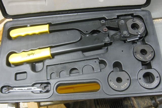
Today there are at least 6 different methods (soldering, compression, glue, pex – cinch, pex – crimp, pex – expander, sharkbite) to connect water pipes and fittings, and there are at least 4 different pipes to choose from – copper, cpvc, pvc and pex. The house has cpvc ¾” pipe and I decided to use pex-crimp and transition with sharkbite. If this all sounds like gobblydegook I will try explain. CPVC is a plastic type pipe, somewhat flexible which is glued into fittings. Unlike PVC, it is good for hot as well as cold water and the glued fittings seem reliable and are cheaper than copper/bronze fittings. But once glued, it is glued and you have to cut the pipe if measurements were off or a change of mind. Sharkbite is expensive but easy to assemble just push the pipe all the way into the fitting and you are done, and it is easy to later separate the pipe from the fitting. And sharkbite is a great way to transition from copper to cpvc or to pex. Pex pipe (a form of polyethylene) is flexible like CPVC. For the pex-crimp method you position (carefully) a copper ring near the end of the pipe, insert a fitting into the pipe, and with both hands position the clamp mouth of a large tool over the ring and (with some effort) close the arms of the tool which crimps the ring tight over the fitting. And then you are done. Pex-crimp is cheaper than sharkbite and a nice feature is you can loose fit and position all the fittings and when you are satisfied then crimp all the rings on the fittings. And after it is crimped you can still rotate the pipe if necessary. And, if you make a mistake (I haven’t yet) you can cut off the ring and re-use the fitting.
my pex crimp ring tool with adapters for 3/8″, 1/2″, 3/4″ and 1″
A disadvantage with pex is the fitting goes into the pex pipe and this reduces the internal diameter of the pipe and impedes water flow more than with copper and cpvc where the pipe goes into the fitting. In London I used a pipe bender for 15mm (0.6″) and 22mm (0.9″) copper pipe which produced wider bends and less water friction than elbow fittings. So now it bugs me to use 0.75” internally restricted pex pipe for the main flow to the house. I considered transitioning to 1” pex but there was less availability and greater cost, so I decided to wait and see.
installation
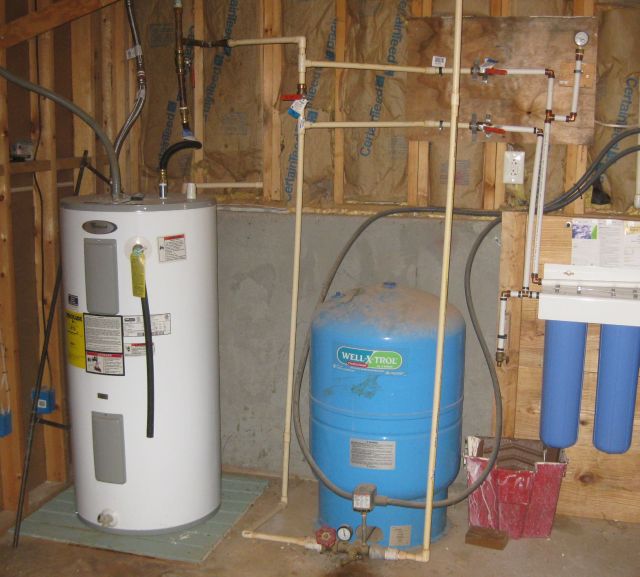
First I had to decide where to mount the 3 stage filter in the basement. It would have been best between the expansion tank and the water heater but there was insufficient space so I reluctantly decided on the right side of the expansion tank. Reluctant because it took the water flow through a number of 90 degree bends.
here is the setup – well water enters blue expansion tank in middle then is diverted to blue filters on right then returns to feed hot water tank and house on left
Next, how to secure to concrete wall. I considered concrete anchor bolts but decided to install a wood wall against the concrete basement wall. I bought a 12ft long, 2” thick, 12” wide (nominal) plank, cut into 4 boards each 3 ft long and stacked them horizontally (see pic above) and held vertically in place by 2×4’s at each end. The top of the top plank rose above the concrete apron wall and I secured it with 7” bolt screws into the base of the vertical wood studs. I screwed the filter housing to the wood wall.
Next for the plumbing. Below is a schematic of the installation:
The blue colored pipe lines are what I installed plus valve A. When valve A is closed, water flows through C to the filters and then returns via B to the original pipe. I can bypass the filters by closing B & C and opening A. I used CPVC all the way to sharkbite valves B & C since I know that glued CPVC will not leak and I am still learning with pex. Pex commences from valves B & C to the filters. I installed a 4th valve at D which allows me to bleed the system (after closing B & C) for removing valves, winterizing the system if I am away, and to inspect the quality of the incoming water. In addition to the existing pressure valve at E I installed another valve at D. As sediment accumulates in the filters there will be a difference between D (higher) and E and when it is greater than say 15 psi, it will be time to change. As previously mentioned filters 1 & 3 are the sediment filters and 2 provides the oxidizing action to precipitate out the ferrous.
Water flow seems fine notwithstanding all the 90 degree turns although I may, one day, replace the line from filter outlet to B with 1″ pex. I bled the water heater and it produced a lot of really brown discolored water which accumulated over the years.
discharging some of the water heater
And now that I have clear water throughout the house I will replace the clogged aerator inserts in the faucet spouts. So far so good.
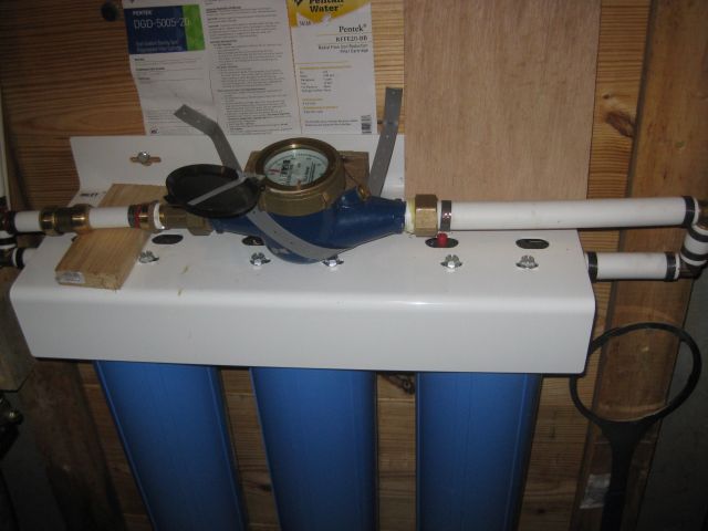
postscript – see my post dated Sept 9 for water loss issue I identified and corrected. Which made me think that I really needed to install a water meter. I happened to have one handy and I used 1″ pex from the filter through 2 90 degree elbows and then returned to 3/4″ pex. See picture below for result.
the new water meter is secured on top of the filter assembly. 1″ pex from filter then 3/4″ pex to house
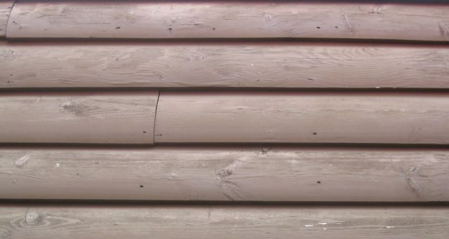
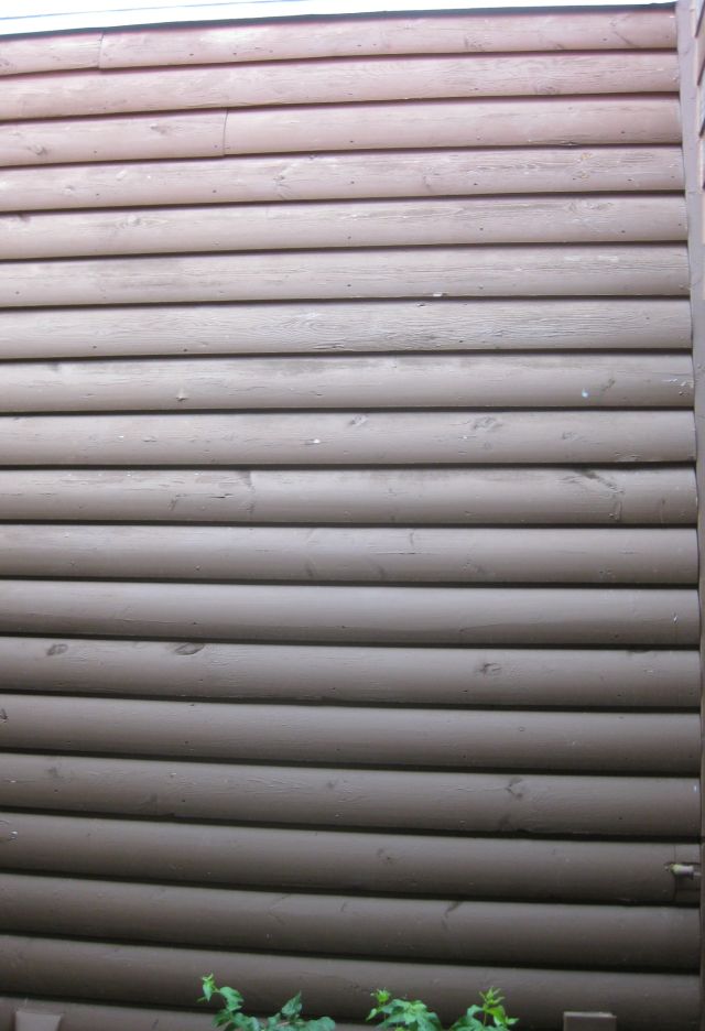
The house on the property has D log wood siding. The “D” describes the shape of the log as seen in cross-section, one side is flat and the other has the shape of a D. The house was built in 2002 and when I purchased it 10 years later the siding was neglected. I engaged a well recommended painting contractor who provided a 5 year guarantee. He recommended, rather than a transparent varnish which would show the wood grain underneath, that we use a block stain which required less annual maintenance. The first day they pressure washed the exterior with a bleach solution – actually sprayed is more accurate since the black mold and loose paint was not disturbed. I took photos showing black mold remaining on the surface and contacted the manager and questioned whether it made sense to paint on top of black mold. With much patience he assured me they were professionals, they had “killed” the mold and it was a good base on which to paint, they knew what they were doing and all would be fine. Each subsequent year paint peeled off and the only comfort was they came back each year and after the obligatory pressure wash/spray ($250) did some scraping and repainted. Aggrievedly they told me they were losing money on each visit. I had little patience. I pointed them to the barn which I had pressure washed and scrubbed before painting and which for 5 years had retained a pristine appearance. They provided imaginative explanations which held them blameless as to why the barn looked good and the house did not. Then the 5 year guarantee ran out and I was on my own.
I try to be self sufficient but scraping and painting from a ladder 3+ stories high does not appeal. And M. provides frequent horror stories from hospital roundings of guys my age who fell off ladders and are now done.
So what to do? I should mention that after the third year, peeling paint was a problem only on the sides facing the summer afternoon sun (west and north). The first two years it was a problem most everywhere because they had not properly prepared the surface before painting. But once they had scraped the loose paint and repainted, it was the sides facing the afternoon sun that deteriorated.
can you spot the difference – the wood top half catches the afternoon sun, the bottom half is largely shadowed by the car port
I remembered in New York I had a similar problem and solved it by applying oil based primer as the foundation on the wood surface and then regular latex paint. Perhaps this would also work in the South?
But who would do a thorough paint job for me? I contacted a local contractor but he didn’t impress and the quoted price for just the chimney and a small area was ridiculous. I spoke to a guy who looked like a painter (skinny, the previous guy was overweight) and he was motivated but did not have insurance. Does my house insurance cover a painter fall? The answer from the broker was confused. I decided if any painting was to be done, the painter had to have adequate insurance. I had my neighbor over who builds log homes and he said wood siding needs annual maintenance and I should go with HardiePlank type siding (allura fiber cement siding) which he could install.
the vexing blunder
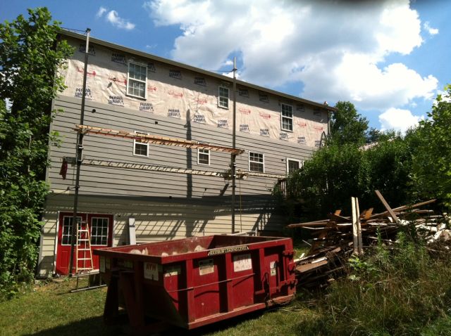
I mulled this over and suggested we leave the D log siding on the lower 2 levels and just do the 3rd level and gables in fiber cement siding. My thought was I could easily maintain the lower 2 levels. He said this would look silly and M. agreed with him, so I gave the go ahead. We agreed on 3 phases – the chimney first, then the long north side and finally the east/west sides. Most of the siding on the south side is covered by roof overhang and is easily accessible and in good condition.
the chimney was intricate and took 2 days, here they are removing the old wood siding
Then came the long side of the house which was also competently done.
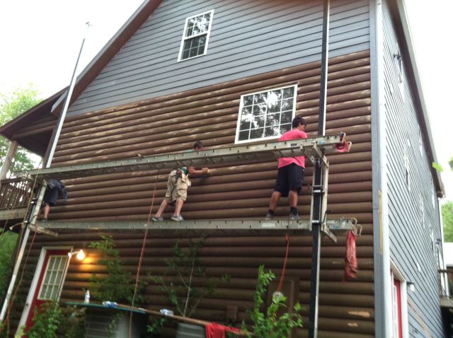
the contractor used pump jack scaffolding – platform is raised by a foot pump operated simultaneously by an individual at each end, and lowered with a hand crank
Weather was in the 90’s and after the north side was done I made an upsetting discovery – the a/c took longer to cool down the house. I went outside and leaned a 5 ft fiber cement siding and a 5ft D log board against the north side of the house facing the sun. Then placed my hand on the sun facing sides – both very hot, then the shadowed sides – the cement board was hot, the D log board only warmish. So the wood board had greater thermal mass and that’s why the house had always been so well insulated in the summer and the winter. I felt sick, my first priority has always been to conserve – energy or rainwater, and now I had unwittingly removed good insulation. I delayed the next phase and pondered what to do. Eventually I decided to have fiber cement board on just the 3rd level and gables of the east and west sides, and leave the wood in place on basement and ground level. And the contractor suggested it would help some if I caulked all the windows and doors which abutted the fiber cement siding (apparently it is accepted practice not to caulk these areas).
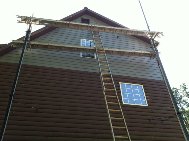
the east side is 3 levels plus gables, you can see the paint work on the remaining wood siding has slightly deteriorated
Since the scaffolding would be lowered after the fiber cement siding was installed I suggested extra payment if they would sand and paint the peeling areas. The contractor agreed.
with the scaffolding already in situ, it took little time to power sand the peeling paint areas and repaint and this saved me the chore
Worth mentioning – yes I got proof of adequate insurance coverage, the flashing was also replaced with fiber cement boards and I pre-painted all the siding before it was installed. Finally on the west side I sanded to bare wood all the boards exposed to the setting sun using a 5″Makita disc sander 4,500rpm with #50 and #80 7″ abrasive discs, which produced some circular scarring. I then painted with oil based primer, then latex primer, then 2 coats of acrylic flat paint. Time will tell if this treatment holds up to the fierce Georgian summer afternoon sun.