
6 years ago I wanted to receive TV via antenna. We have DSL and I can access Netflix and YouTube etc. but not local stations. I positioned the antenna facing south (Atlanta’s direction) about 20 feet off the ground and connected a cable from the antenna to the cable attached to the previous owner’s dish receiver, and in the winter received a few stations. Since I have digital TV and the signal is digital I do not require a converter box. In the summer reception fell off because the trees grew leaves. I lost interest in the project. Now I have re-engaged.
some technicals
I input my street address at website “antennaweb.org” and it tells me which stations can be accessed and their direction relative to my house. Most are from Atlanta about 40 miles distance. The website “tvfool.com” provides more detailed analysis of nearby channels including the signal strength (Noise Margin decibels– NM(dB)).
I have grappled with but never understood dB (decibels) which is a measurement of the intensity of sound. It is about logarithms, a weak area for me, except that I remember that instead of multiplying two numbers you can take their logs and add them together and the antilog gives the result of multiplication. If the intensity of sound falls by half so the output is (0.5), the input, this is described as a 3 dB fall – the log calculation is 10log 0.5 i.e. take the log of 0.5 and multiply by 10 and the answer is -3.0dB. As the TV signal wends its way through the house to the TV it loses strength – if you wish to power 2 TV’s you use a splitter to split the input into 2 outputs and a consequence is the signal is reduced by half which is 3dB (usually 3.5dB is used in calculations). If 100 ft of RG-6 cable is used and the frequency carried is 700MHz, there is a further loss of 5.6dB, so total loss is 9.1dB (-3.5dB-5.6dB). If you add an amplifier at the antenna end which has a rating of +8dB, then the net loss is 1.1dB. So a nice feature using dB is you simply add up the gains and losses and ensure your signal strength is not too diminished on its way to the TV. You could also use a dB signal meter which is now offered for <$100 (used to be >$500) but not worth the investment for one time use.
I mention that signal loss in the cable is affected by the frequency carried. The impact is significant – for example the attenuation (reduction) to a 50MHz signal on 100ft RG-6 is 1.4dB and for a 900MHz signal is 6.0 dB. A 200ft cable has twice the loss, a 50ft cable half the loss. Which raises the question – what is the frequency of the stations I receive?
There are two bands VHF and UHF. VHF for the 2 stations I receive, has frequency range between 174 and 216 MHz, and the UHF frequency range is between 470 and 890 MHz. Almost all the channels I receive are UHF. So when I design my system I have to ensure it will adequately handle frequencies up to 900 MHz.
back to installation
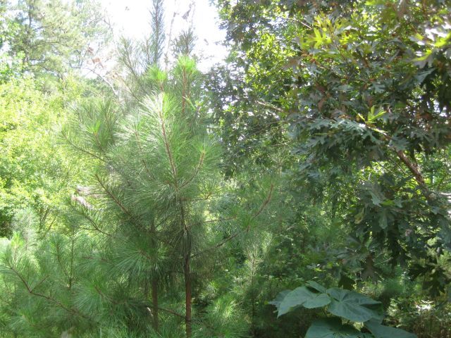
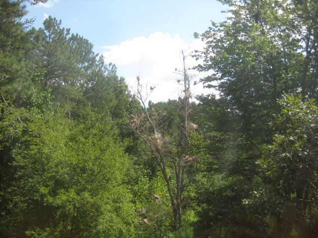
As mentioned, in summer the view of the antenna was blocked by branches and leaves, shown below:
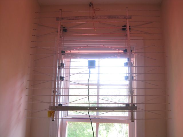
Rather than attach the antenna to the chimney (lightning hazard?) or locate in the attic (signal interference from steel roof?), I moved it to a south facing dormer window.
The old antenna was too wide so I snipped off a couple of inches from each side and suspended it from the ceiling.
Next step was to connect the antenna to the TV in the living room. I decided to use the existing RG-6 TV cables in the house since every room had been wired for TV and there was a nearby outlet. I connected a battery to the outlet and headed for the basement and located the cable which carried 9 DC volts. I did the same in the living room and then knew which 2 cables to connect.
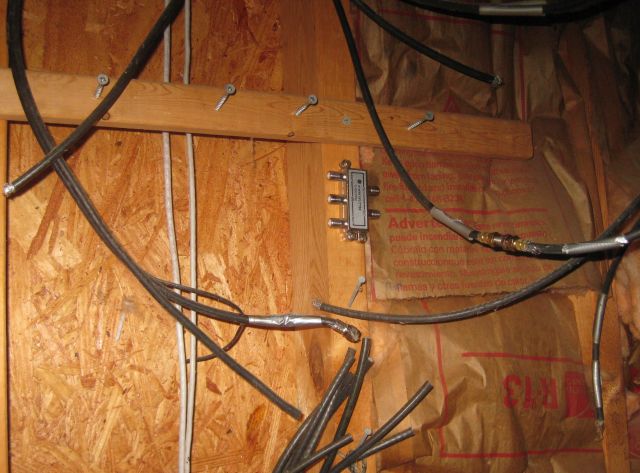
Not knowing better at the time, I used 2 splitters – 1 for connecting upstairs cables and 1 for the basement cables.
I instructed the TV to scan for digital channels and it found 8. I thought I could do better and decided to eliminate the 2 splitters since I was only using 1 TV in the house, and directly connect the cables together.
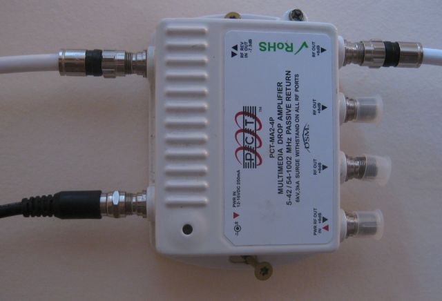
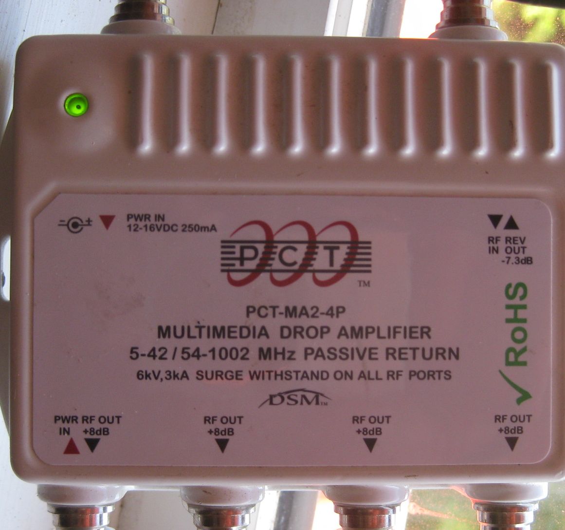
The TV now located 18 channels. I was on a roll. I remembered I had once purchased a signal amplifier so I connected it at the antenna end and the TV was now able to locate 34 digital channels.
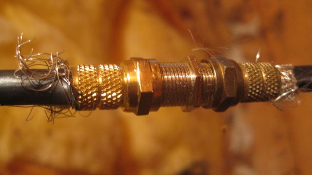
Could I do even better? This far I had incurred no cost – the screw on cable connectors, stub RG-59 cable and the signal amplifier were leftovers from previous projects. The screw on cable connector not only looks amateurish but has a practical disadvantage – you twist it clockwise onto the cable and then you twist its rotating cap clockwise onto the male thread of the TV or antenna or connector. And the 2nd twisting motion is opposite to the first and unless you are careful you can loosen the grip on the cable and weaken the connection. So I ordered for for about $20 a package containing a stripping tool to remove the sheathing on the cable, a compression crimping tool which compresses fittings on the cable, and blue locking compression connectors. For good measure I also ordered an additional 50 black connectors for about $10. I also decided to replace the RG-59 stub cables with RG-6 which is a thicker cable with better insulation for higher frequency signals and the 20 ft length of black RG-59 in the living room was conspicuous against the white walls. So I ordered 100 ft of white RG-6 for $16. I had now invested just under $50 and was hoping for better reception.
I replaced the 3 stub cables (antenna to amplifier, amplifier to upstairs room cable, living room outlet to TV) with RG-6 cable and the twist on cable connectors with the attractive blue compression connectors. Instead of 34 channels my TV now scanned 14 channels. This was a setback. I remembered the basement connectors were twist on cable and found one was loose and replaced them with blue compression connectors and I now go 18 channels. It seemed one of 3 things could be wrong – the cable was bad, the connectors were bad or my technique was bad. I reexamined all the connections and found one I had forgotten to compress.
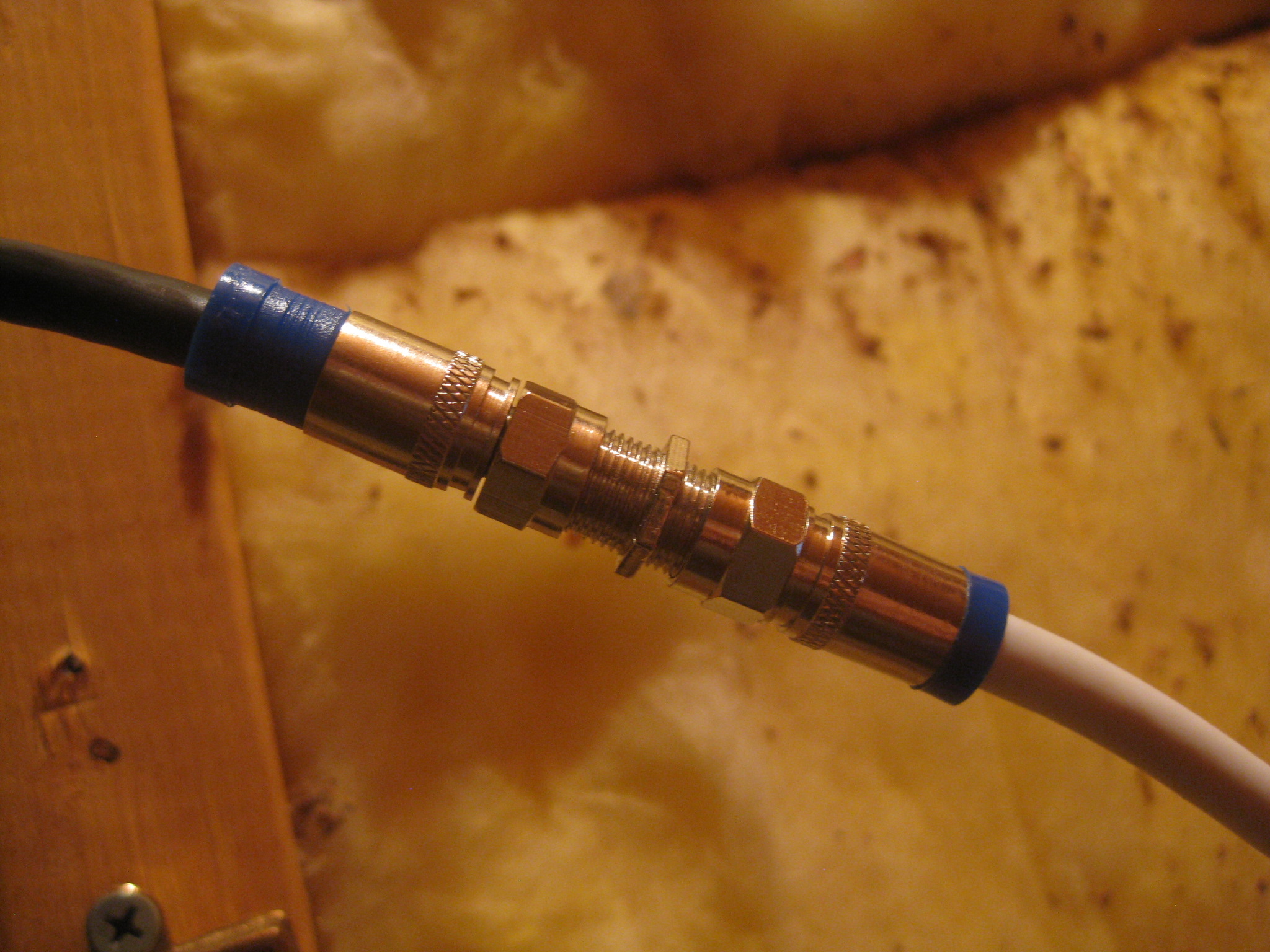
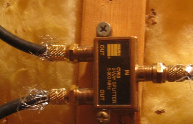
You can see the connector on the left was not compressed, so I compressed with the compression crimp tool and the TV located 24 channels, 11 less than with the old cable and connectors. I examined the cable and it clearly stated it was RG-6 and I concluded it could not be the problem. Then I examined the blue connectors and found each had a rubber ring inside the threaded female twist cap. The ring probably protects against moisture but it could also block end on end electrical contact. Perhaps this was the problem? So I replaced 9 blue connectors with the new black compression connectors. And…
And I now have 43 channels and am happy.