lawn tractor transmission problem

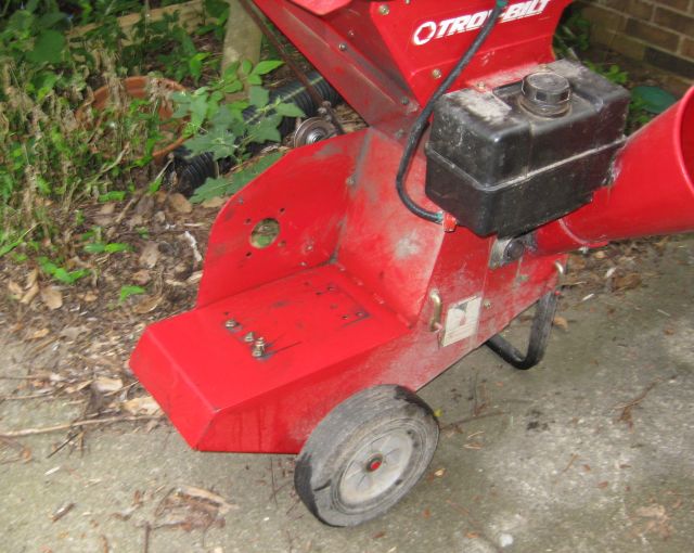
When a neighbor departed I purchased from her a Murray 14.5hp 40″ lawn tractor.  The engine fired but the tractor wouldn’t budge.  After some basic repairs I got it running fine and have kept it going the past 3 years.  Since I use it over rough ground it occasionally needs repairs – such as replacing shattered mandrels when the blades hit concealed rocks, beating out the housing from rock collisions and replacing the mower drive belt.  I now use my big tractor with a pto bush hog for the rough ground and tough grasses, and hope to nurture this lawn tractor along and use it for more confined areas such as the chicken paddocks and between the fruit trees.  I also use a scythe for occasional clearing.

All was well until a couple days ago when after cutting a chicken paddock area and closing the gate, I shifted the gear selector to forward and, though the engine continued to run, the tractor was stationery.  I selected each of the other forward gears and the reverse position and the tractor did not move.  A new challenge.

Today I worked on the tractor.  My reasoning was the problem could be one of 3 things:  the gear lever was not communicating with the transaxle (transmission); the transmission was defective; the transmission and the gear lever were fine but the transmission was not receiving power from the engine.

First step was to access the transaxle.

view of rear of lawn tractor showing rear wheel, transaxle and below upraised seat, the battery housing
view of rear of lawn tractor showing rear wheels, transaxle and below upraised seat, the battery housing

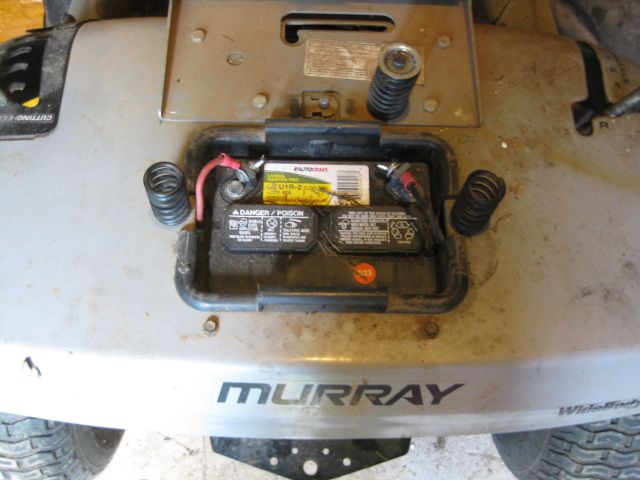
I disconnected and removed the battery from its housing.

a simple step to remove the battery - disconnect the terminals (negative first) and then lift and remove
a simple step to remove the battery – disconnect the terminals (negative first) and then lift and remove

With the battery removed you can see the big pulley which is attached to the transaxle.  The engine at the front of the tractor turns two drive belts – one belt rotates the mower blades and the other, which is well concealed, provides the power to drive the wheels via the transaxle.

with battery and housing removed you can see the drive pulley attached to the transaxle

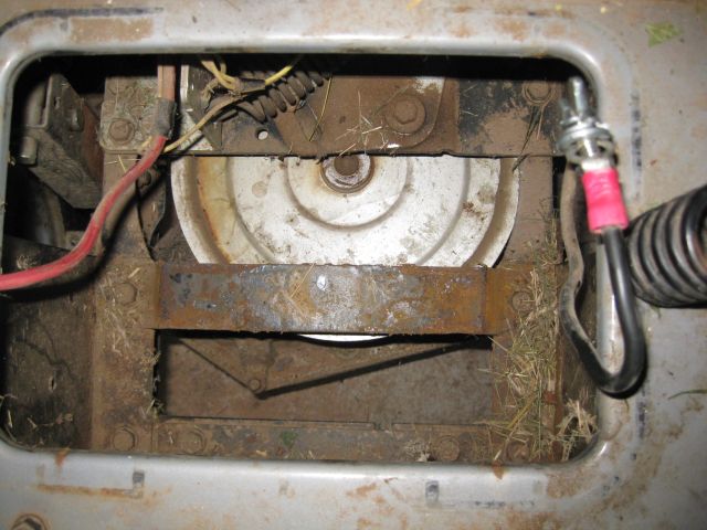
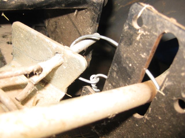
Also visible above the pulley is a large spring.  This is attached to the idler pulley.  There are three pulleys – the pulley the engine turns, the pulley attached to the transaxle and the idler pulley which keeps the belt taut when the tractor is moving.

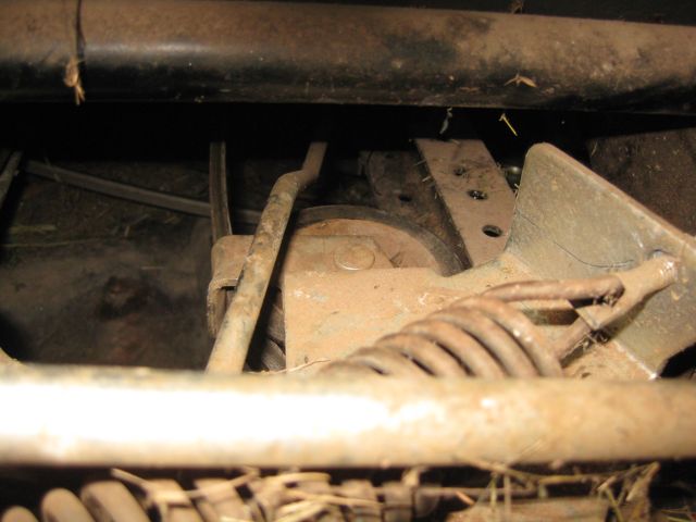
So what was wrong – there was a belt on the big transaxle pulley so it seemed the transaxle must be receiving power from the engine.  I selected a gear and pushed the tractor and to my surprise the big pulley turned.  I put the gear selector in neutral and pushed and the pulley did not turn.  I selected reverse and pushed and the pulley turned again but in the opposite direction.  I then breathed a big sigh of relief.  The gear selector was working, the transaxle was working and the belt must be loose.   I navigated to the engine end and felt underneath and found the pulley which drives the belt to the transaxle and the belt was also there and intact but it was not on the pulley.  So the belt had come off the pulley.  Now why had this happened.  In maneuvering my hand under the engine I pulled on the engine and it rocked forward.  It typically has 4 engine bolts and the rear two were missing.  Incidentally when I first got the tractor the same 2 bolts were missing and I replaced them – so I was familiar with these bolts.  I surmise that when I engaged the gear the engine rocked forward which meant the pulley underneath rocked back and the belt came off.  Probably also because the belt has stretched.  Rather than replace the belt I decided, for the time being, to reseat the belt and order and install the 2 missing engine bolts.

But it is very difficult to work on the pulley under the engine – it is barely accessible and there is no room to apply leverage on the belt to force it back onto the pulley.  Then I remembered the idler pulley – if I could move it aside it would free up a lot of belt slack.  I tried approaching the idler pulley from underneath and then concluded that a long crowbar via the battery housing   would secure a good grip and move it aside, which it did.  But I could not hold the crowbar in place at the rear of the tractor and reseat the belt under the engine at the front of the tractor at the same time.  I needed a helper.

a view of the idler pulley, limited access space

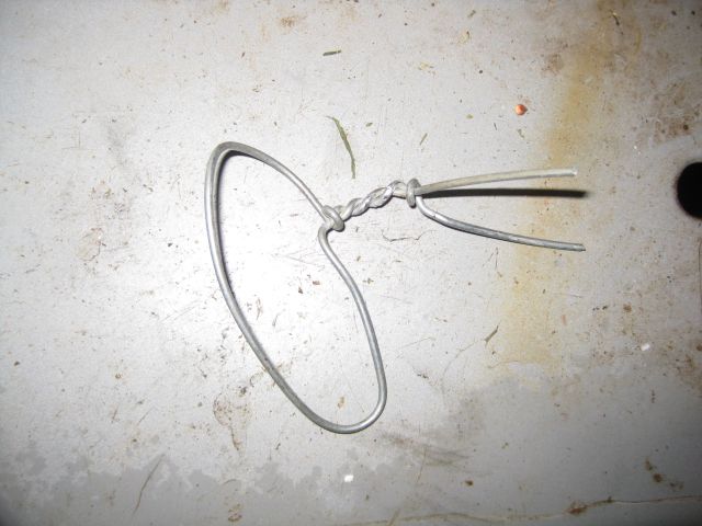
I cut a piece of strong wire and shaped it into a loop.  Then with the crowbar I pushed the idler pulley to the side and with the wire band secured part of the idler assembly to the shaft of the gear selector which acted as my anchor.  With the idler pulley now held out of the way by the wire band, it was then a simple matter with one hand to reseat the belt over the engine pulley.

you can spot the wire band which is holding the idler pulley assembly out of the way of the drive belt
here is the wire loop or band which was my assistant with this repair

When the engine bolts arrive I will complete the repair and in future make a careful check that all the engine securing bolts are in place.


seized engine repair

how I diagnosed and repaired a seized engine

I heard of  a seized engine and hoped never to experience one.  And then my luck ran out.  Not really a matter of luck as carelessness.  At the Atlanta house I use a chipper/shredder for branches and foliage en route to the compost heap.  The shredder has functioned flawlessly since 2000, except for one bearing which was easily replaced.

chipper with seized engine
my 10.5hp Troy-Bilt chipper/shredder – branches chipped through the long funnel and foliage shredded through the hopper at the top

I regularly checked the oil level – by positioning the machine on level ground, removing the oil plug and ensuring the oil was level with the lowest threads for the oil plug.

the offending yellow oil plug and the oil check tube into which it is threaded

And then one morning, while chipping away, something unusual happened – the engine puttered out.  I thought it was short of gas but there was gas enough.  I tried cranking it by pulling the starter rope and it turned easily – too easily.  I assumed either the rope was not turning the engine – a quick check told me it was, or that the engine had lost compression.  And then I noticed that the yellow oil plug was missing.  And surmised that as I was operating the machine it had dislodged the oil plug, pumped out all its oil through the oil plug hole and then became a seized engine.  Initially I hoped that the valves (there are two one for intake and one for exhaust) had stuck in the open position and this was why there was no compression.

the intake and exhaust valves, but the I had a seized engine
the intake and exhaust valves

But the valves were fine, so it had to be the piston.  I removed the spark plug and inserted a pencil through the spark plug hole and found the piston.  I pushed down on the pencil and the piston slid down the cylinder.  So, good news – the piston was not seized/melted onto the cylinder and bad news, the rod which connects the piston to the crankshaft was broken.  I had a seized engine.
Next step – 3 options: a) trash the chipper – it had given me many years service and I could transport branches to my farm and use my large tractor driven chipper; b) buy a replacement engine – cost approx $350 before transport costs; c) fix the engine.  I opted for (c).

Disassembly
Relatively straight forward to remove the engine from the chipper frame.

chipper with engine removed for seized engine repair
chipper with engine removed

I took the engine with me to my farm – something to do in the basement during the middle of the hot summer days.

seized engine in transit 0806
seized engine in transit to the farm

Also straightforward to disassemble the engine.  I rethreaded screws and washers where possible to minimize the conjecturing effort required during assembly trying to figure what goes where.

obvious damage visible when crankcase cover is removed
obvious damage visible when crankcase cover is removed – the results of a seized engine
another pic of the damaged parts
another pic of the shattered parts from the seized engine

It appeared that  with my seized engine the piston rod disintegrated – parts of the aluminum rod were melted onto the crankshaft journal.  I removed the piston and felt the interior of the cylinder.  No noticeable scoring – phew – minimal damage for a seized engine, so all I had to do was buy a new rod, new piston and rings and gaskets and sand the fragments off the crankshaft journal.  I thought the replacement parts would be inexpensive, but they cost in total approx $90 from the cheapest internet supplier.

I scoured the internet and found a free downloadable workshop manual for Briggs Stratton engines including my model.  This was immensely helpful for all the subsequent procedures.
The piston assembly came with piston rings, which have to be fitted, but no piston pin bearing which is the pin which connects the rod to the piston.  So I removed the pin from the damaged piston and I then connected the rod to the piston using this pin, ensuring that the arrow on the piston pointed toward the “mag” on the rod as directed by the manual.

Next step was to install the piston rings.  There are 3 grooves.  On the bottom grove goes the oil control ring and on each side of it, two thin rains.  The center ring goes into the middle groove.  It has two paint stripes and they are installed with the stripes to the right of the ring gap.  Finally the top ring is installed in the top groove of the piston.  It has one stripe which is installed with the stripe to the right of the ring gap.  friend lent me his ring compressor –  it was a simple matter to tighten the rings with the ring compressor and insert the piston with the rings into the cylinder. 

piston rings are compressed as the piston is slid into the cylinder

Connecting the rod to the journal
The torque specs for the connecting rods is 100lb-in and my 0.5” torque wrench only goes down to 20lb-ft which is the equivalent of 240 lb-in (multiply by 12).  So I have to pause my rebuild until I have acquired a 0.25” torque wrench which is calibrated for 100lb-in.  At my favorite internet shopping site I surveyed the 0.25” torque wrenches available.  There are expensive wrenches costing more than $100 and presumably these are superior to the <$40 wrenches.  I am hopeful that I will not have to repair too many engines and so, after reading numerous reviews I purchased the new model Tekton, which arrived quickly and appears well made and up to the task.

My plan is to secure the bolts into their threads using loctite which is a special glue made for this purpose.  I have learned from bitter experience that for important tasks I should do a trial run first – so instead of applying the glue to the threads and then torquing each bolt to 100 lb-in, I first torqued the bolts without the glue.  At 100 lb-in the piston wouldn’t move.  So I backed off the torque to 50 lb-in and the piston still wouldn’t move.  I concluded that the sanding I had previously done was insufficient and there was still a coating of the aluminum from the rod cap on the crankpin journal.  So this meant a lot more sanding. 

hand sanding the crankshaft journal, with a piece of wood to prevent rotation

I figured out how to sand the journal effectively without removing the assembly from the block – I sanded with my hands pulling the sandpaper down and with the journal in four different positions  90 deg, 180 deg, 270 deg and 360 deg, initially with 180 grit paper until there was no aluminum residue and then with 220 grit and finally 340 grit.  I retorqued the rod cap bolts to 100 lb-in and the piston moves, so after this detour I can move forward again rehabilitating the seized engine.

Valve grinding

 Since I have dismantled the engine and the engine was used for more than 12 years it seems appropriate and convenient to regrind the valves.  I first removed the rockers which blocked access to the valves and their springs.  The difficult bit is releasing the valve stem from the spring which holds it tight against the cylinder head.  I have a valve spring compressor but it is really meant for car engines where there is more space to use it and the car springs are stronger.  So after maneuvering unsuccessfully with the valve spring compressor,  I simply pressed down with my thumbs on the valve spring retainer and removed the two retainer rings (actually one hurtled across the room and was eventually located).  I applied some valve grinding compound onto the valve and using an old valve grinder from my London days, rotated each valve quickly back and forth in its seat. 

hand operated valve grinder for seating the valves

Then I compressed the springs and reinserted the retainers.  

So, with the repair work done it was just a matter of assembling the engine following the torquing  specs in the manual, and then attaching the engine to the chipper and starting it up.  It started immediately but there was a problem – the engine was racing.  A whole new field for study – how the governor works.
The throttle on the carburettor is held in the open position by a spring.  Open position means there is no obstruction to air entering the carburettor which means the engine goes faster.  But if the engine goes too fast it will be damaged.  You only want to open the throttle when the engine is under load such as chipping.  So the governor is a clever device – as the engine speeds up, centrifugal weights slide outward and their motion via linkages counteracts the pull of the spring.  When the engine is chipping it slows down, the centrifugal weights slide inward, the governor ceases to oppose the spring and the engine speeds up.  It took me some time to figure this out and how to correctly set the governor.  My repair of a seized engine is concluded, the chipper runs fine for now – the real test will be for how long.


truck maintenance – changing the spark plugs

I have a  base model, no frills, manual transmission wind up window 2005 Toyota Tacoma pickup purchased new in 2005 for approximately $14k.  It now has 160k miles and, apart from replacing the tires, I have done all the maintenance work.  Which has been minimal – such as oil and filter (I always include a qt of fully synthetic oil), new battery, windshield wipers.  Because the miles are highway miles, the brakes have been rarely tapped and therefore have not required replacement.  And, these being truck tires, tire replacement is after more than 60k miles.  A very economical vehicle with good mileage per gallon.

The recommendation is to replace the spark plugs every 90k and I bought 4 new spark plugs as the mileage approached that mark.  The replacement procedures seemed complicated and, since the truck went fine and I was lazy, I deferred the moment.  Recently the truck has lugged while going up hills  and seemed to need more gas pedal encouragement than usual.  So yesterday with the mileage gauge almost on 160k miles,  I decided to get on with the job.

I used the Haynes Repair Manual for my vehicle and followed the step by step illustrated procedures.  In the past I did not need a repair manual – simply follow the spark wire to the plug, carefully pull the wire connector from the plug, remove and replace the plug (after gapping) and reattach the wire.  Problem with modern vehicles is they do not have spark wires but ignition coils and above the ignition coils there is superstructure which must first be removed.

engine before removal of any components

So the first steps (after disconnecting the negative lead to the battery) were to remove the air intake duct or large pipe which connects the air filter housing on the left to the intake air connector, which sits above the engine.  Then numerous electrical connections, a vacuum hose and a fresh air inlet hose had to be carefully disconnected from the intake air connector, which was then itself removed.  I have learned that the key with removing all these items (apart from not losing them or forgetting how to connect them back again) is to use gentle and intelligent force. And also to have the right tools at hand.  It is so easy to break a connector especially after it has been in use for more than 7 years and has become somewhat brittle.

the engine with the intake air connector removed and the wires leading to the ignition coils exposed

Next steps were, to remove the ignition coil starting with the easiest most accessible ignition coil and using a lot of care not to damage anything. Not having done this before, I had thought the ignition coil sat just above the spark plug.  As the photo below shows, where it is compared to a spark plug, it is actually a long tube.

ignition coil on right which fits over and onto the spark plug

Once I got the knack for disconnecting the electrical connector it was quick work to remove and replace all 4 spark plugs.  I was relieved to see that all the plugs were in good condition with no signs of oil, carbon, or ash deposits or anything untoward, except for electrode wear.  Then I followed the disassembly instructions in reverse (my memory which was never that great could not be trusted to locate and connect all the fittings), re-connected the battery and started the motor.  And it goes great – takes the hills with gusto and requiring little encouragement.

Inspired by my success I also tackled the task of adjusting the parking brake.  With time the cable had stretched and the parking brake could not be relied upon to hold the truck in place on even gentle slopes.  This task took almost as long as replacing the plugs.  To adjust the brake you have to remove the center console (where the manual shift lever is) and slide the bench seat back.  Clearing the center console of its accumulated contents took time enough.  More time was needed to remove all the equipment (chain saw, machete, crowbar, tools, kits, straps etc.) and debris, accumulated over 7 years, behind the bench seat.  The center console removed easily, the carpet was shifted aside, a cover plate unscrewed and it was quick work to adjust the parking brake cable.

A dealer had quoted either $120 or $180, I forget which, to adjust the parking brake – it was an unsolicited quote provided when I took the vehicle in for a minor recall (why are there so many recalls?).  I have no ideal how much replacing the spark plugs would cost – the spark plugs (platinum or iridium) are not cheap and I suppose this would also have been in the hundreds.  I felt good doing this myself with no complications – feels good to be self sufficient and also to save money.

gumption and the intermittent failure

If the South’s summer heat and humidity bear any consolation, it is that I have to seek shelter in the house for much of the day and thus am able to extend my reading.

I enjoyed the first third of Zen and the Art of Motorcycle Maintenance by Pirsig but struggled as the protagonist ascended higher into the mountain and into rarefied philosophical issues for which I was not prepared.  Now in the last third of the book the running is easier.  His thoughts on gumption and practical issues of machine maintenance bring back memories.

At p. 310 he says “I like the word “gumption” because it’s so homely and so forlorn and so out of style it looks as if it needs a friend and isn’t likely to reject anyone who comes along”.  I recall “gumption” too with affection.  The only time I heard it used was by Tommy Cairns our lecturer in cost accounting at my university in Johannesburg during the early 70’s.  His lectures were punctuated by reference to a general lack of gumption and the criticality of gumption for success.

Now, many years later I see it dancing on the pages of Pirsig’s book before me, such as “Gumption is the psychic gasoline that keeps the whole thing going.  If you haven’t got it there’s no way the motorcycle can possibly be fixed.  But if you have got it and know how to keep it there’s absolutely no way in this whole world that motorcycle can keep from getting fixed.”

One of the gumption traps he refers to is the “intermittent failure” which fools you into thinking you have an engine problem fixed and then it recurs.  He suggests methods to identify and fix the problem with the advice that “In some intermittents you have to resign yourself to a long fishing expedition, but no matter how tedious that gets it’s never as tedious as taking the machine to a commercial mechanic five times”.

All of which brings back my second memory.  When I lived in London I had a Morris Minor – a two door beetle-like friend (formerly a police car) which I worked on extensively and affectionately called “Elbee” for its licence plate.  Elbee developed an intermittent fault – when I rounded corners quickly the electrics would falter.  I searched everywhere for the culprit, without success.  Elbee’s tools were kept in a rollup bag and one day, upon lifting the bag, I noticed an aimless, loose wire beneath.  This was an earthing wire held in place by the tool bag and I figured that when I cornered and put Elbee through her paces, the bag shifted and the wire lost contact with the frame.  It was an easy fix to secure the wire.

gumption
Elbee receiving a new clutch. The suburban street was my workshop

shear bolts

recumbent subsoiler, flanges on right had twisted

When I first began using my tractor I did not appreciate the importance of shear bolts or patience.

I have a Case 585 tractor, which was built in the late eighties and has a 60hp 4 cylinder diesel engine.  I needed to dig a small rain catchment ditch along the gravel driveway to catch rainwater as it streamed down the hill.  Georgia clay in summer is difficult to work, even with a pickaxe.  I decided to facilitate the job with a subsoiler (sometimes also called a chisel plow) attached to the rear of the tractor.  Problem was I went too fast and too deep and I heard a wrangled snap.  The flanges of the subsoiler which attached to the tractor were twisted.  My sledgehammer made no impression on straightening the metal so, reluctantly, I took the subsoiler to the local tractor dealer (where I had purchased it), and within a few minutes all was straightened out (for no charge and probably with the help of a machine press) and I more cautiously completed the job at hand.  The point about this incident is that the subsoiler should not have been damaged, the shear bolt should have snapped first.

post-hole auger in home made frame

The shear bolt is the safety mechanism, like the safety valve on a pressure cooker, which releases the pressure before any real damage is done.  I have a Bush Hog auger which I regularly use for drilling holes for posts (9″ auger) or tree plantings (19″ auger).  When the cutting edge hits a large rock the sudden impact causes the shear bolt to snap.  This is cheaper to replace than fixing a stripped gear box or damaged drive line.  The shear bolts for this auger are tapered (one hole in the yoke is 3/8 and the opposing hole is slightly narrower) which presented a problem a few weeks ago, when I needed a replacement shear bolt and my usual source, the local tractor dealer just a 4 mile drive, had gone out of business.  The next closest dealer is about 30 miles away and instead of making the drive, I wandered fruitlessly around the local and big box hardware stores as well as an autoparts store looking for tapered 3/8 bolts which would fit the yoke.  My solution was to purchase a 3/8 drill bit intended for hard steel and I drilled out the hole in the yoke so that it could accommodate a 3/8 bolt.  Having sidestepped an intended safety feature, this got me wondering whether I could be facing a bigger repair bill than a shear bolt further down the road, when I hit the next big rock.

auger shear bolt in place
pto shaft (black with yellow guard) attached to gear box


I have read the online manuals for the various implements I use and although they refer to shear bolts or shear pins, they don’t specify the grade you should use.  Perhaps the intention is you should buy your shear bolts from the dealer instead of from a cheaper source.  Anyhow, the word on the online blogs is to use grade 2 or grade 5.  The higher the grade the tougher the bolt.  I suppose start off with grade 2 and, if it keeps snapping when the equipment is used prudently, then migrate to grade 5.  You can tell the grade of the bolt from the markings on the head of the bolt.  No markings indicate grade 2 and 3 radial lines indicates grade 5.  I shall apply this advice next time I use the auger or my Wallenstein chipper.  My Bush Hog rotary mower has not had a shear bolt snap and this may be because it has a slip clutch which cushions the gearbox and driveline from sudden impacts.

wood chipper
chipper shear bolt (bit too long)