This morning’s wsj 6/21/17 first page article says “Bust Your Phone Again? These Teens Are Here To Help”. A 16 year old Nantucket resident instead of surfing, made close to $24k last summer repairing smart phones and is busy again this summer. His charge to repair a cracked iPhone 7 Plus is $189.99.
M. dropped her iPhone 4 last week and the screen is hard to read – see pic above. She wants to wait for the new iPhone due later this year. So I suggested I would try repair it. On the internet retail giant’s website we ordered a kit comprising new screen and repair tool kit for approximately $17 plus tax. The iPhone 4 is an old phone so replacement parts are reasonably priced. Our phone is a Verizon phone which is different from AT&T, so it was important to order the right screen and also to follow YouTube instructions for the Verizon/Sprint phone not the AT&T.
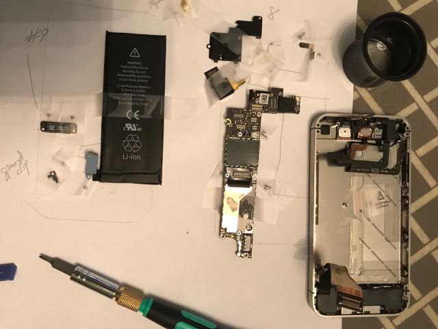
The kit arrived and following the excellent tutorial I began dismantling the phone. There are lots of tiny screws and to keep track I followed a suggestion to sketch an outline of the phone and tape the screws and parts to the location where they belonged.
the easy part – removing the back cover. you can see the 2 torx screws taped below the back cover
I quickly encountered a problem – the Phillips screwdriver provided with the kit was not up to the task. So I stalled for a day and visited a computer store to inspect their screwdrivers. The size I needed was a Phillips PH000 and there were lots to choose from. I settled for a kit made in Taiwan made of chrome-molybdenum, described as professional, with an ISO certification. Perhaps all these plugs would help. And they did – no more problems with screws. And then I stalled again until I read this morning’s wsj article and, fired up, I resumed.
To get to the screen a whole lot of parts have to be disassembled. Not for those faint of heart, or with unsteady hands or blurring close up vision or impatient to get the job done. I could tick some of these boxes.
the guts have been removed and down to releasing the screen from the frame
A hair dryer was conscripted to soften adhesive and then the old cracked screen was off and the new screen installed. On the re-assembly road back I was too confident and went too quickly and missed a few steps and had to backtrack, which was frustrating. But eventually all the components were in place and the critical moment arrived – would it power on and make and receive a call, and it did.
the new screen has a white border, the old a black. but M. is not complaining and is almost adulatory
In addition to my place north of Atlanta where I spend most of my time, we have a large house in Atlanta which we will sell when M. stops working. I have begun readying the Atlanta house for sale. It has two water heaters and neither has an expansion tank. The code requires an expansion tank be installed if a new heater is installed or if a backflow preventer (check or one way valve) is installed.
A backflow preventer prevents water on the house side of the device from flowing back into the main supply. Since the house side is sealed (until you open a faucet) when water expands (from being heated by the water heater) it has nowhere to go and the pressure build up could damage appliances such as the water heater. Therefore the need for a device which can accommodate the expansion of the water. An expansion tank should not be confused with a T&P (temperature and pressure valve) which is attached to water heaters and releases water when the pressure is unusually high.
Expansion tanks are usually connected to the cold water inlet to the water heater. The tank has an air bladder/diaphragm and air valve which looks like the valve on car tires. Instructions suggest inflating the bladder to the pressure of the water in the house. The size of the expansion tank depends on the size of the water heater. Our water heater is 50 gallons and a 2 gallon expansion tank cost $40 is adequate.
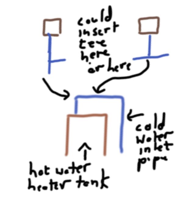
The question is where to add the tee for the tank.
One suggestion was on the 90 degree bend where the tank would have the most support, but this requires unsoldering the elbow and then either re-soldering or scrupulously cleaning the existing pipes to accommodate a SharkBite or GatorBite fitting (“shark fitting”). The easiest was between the 2 elbows and I ascertained there was sufficient room to pull the pipes apart to accept a new tee fitting. Next question was to solder or use a gator fitting? A soldered joint is rigid and regarded as permanent and once soldered can hold the tank in a vertical position. A shark fitting can be swiveled which is convenient at times but cannot hold a tank vertical since the slightest nudge will cause it to swivel down.
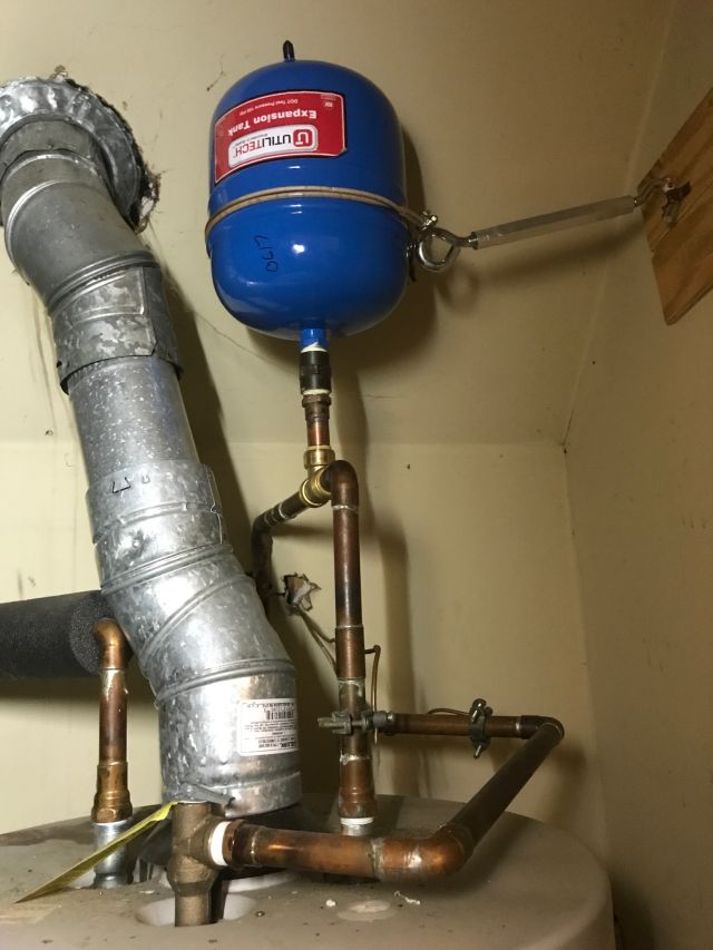
I have done lots of soldering in the past. Solder fittings are much cheaper than shark fittings and are permanent. However, shark fittings are very easy to use and easy to undo such as when you have to replace the water heater. There is a nagging concern that a shark fitting can come undone when I am away from the house, but the literature and others assure me this will not happen. So I bit the bullet and used a shark tee fitting and developed a method to ensure the expansion tank stayed vertical.
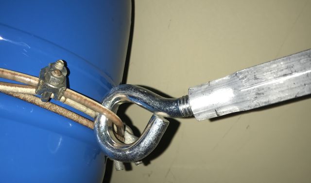
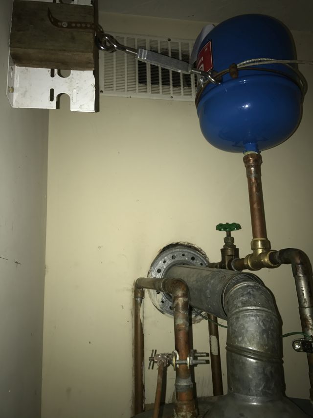
Steel cable is secured around the middle of the tank. A turnbuckle is attached to the cable and to an anchor on a wood plate which is screwed into a stud.
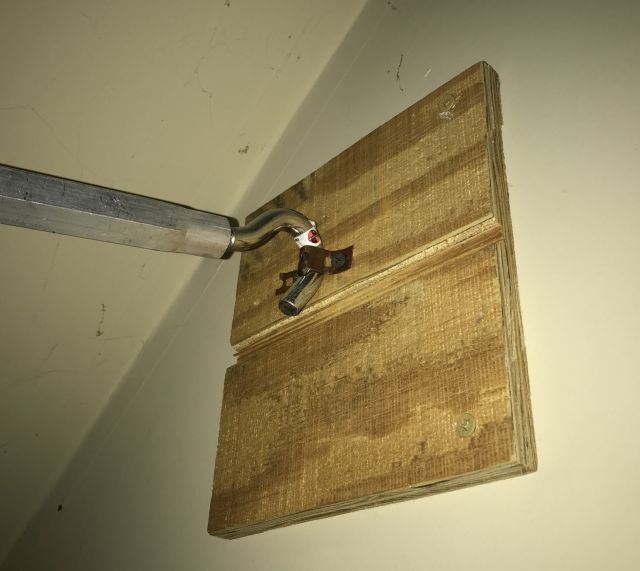
the wood board has screws on the right vertical edge going to the stud. the eye of the turnbuckle is secured by a copper strap screwed to the board
By adjusting the turnbuckle I can assure the tank is vertical.
a close up of the cable securing the expansion tank. I used one clamp for a tight hold on the tank and another clamp to provide a loop to secure the eye of the turnbuckle
I did solder the 3/4″ male fitting which is coupled to the male fitting on the tank. I happened to have a 3/4″ male and coupler available, otherwise I would have simply purchased a 3/4″ female fitting. If I had simply soldered the tee fitting I could have dispensed with the cable, turnbuckle and other bits shown above.
And shown below is the expansion tank on the 2nd water heater.
I reduced the space between the wall and the tank by using a right angle bracket and therefore could use a smaller and cheaper turnbuckle
When not using the truck to transport materials, I use M’s 2007 Camry which now has 155k miles. It is more comfortable and uses less gas. Apart from regular maintenance it has required little extra expenditures – new front rotors @ 98k; new upper engine mount @ 138k; new alternator @141k.
But for some time brake vibration has been an issue- the brake pedal pulsates and the steering wheel shakes when I forcefully apply the brakes. Because the steering wheel shakes this indicates the problem is the front rotors and I had replaced both rotors at 98k. I decided that rather than again replace both rotors (new ones cost about $25 each), I would identify which was the problem and try determine why this was re-occurring.
The brake rotor, also known as the disc, (therefore the term “disc brakes”), is mounted just inside the wheel and rotates with the wheel. The rotor rotates between 2 brake pads held in place by a caliper and braking occurs when the piston in the caliper applies pressure to one of the pads. Since the caliper can move laterally (but not with the rotation of the rotor) the pressure is effectively applied evenly to both pads, which engage the rotor and slow its rotation and vehicle movement. The vibration occurs because there is variation in the face of the rotor on one or both of its sides. This is called runout and for lighter vehicles such as the Camry, runout should not exceed a few thousandths of an inch.
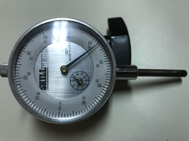
I have a read out gauge -see above and below pictures.
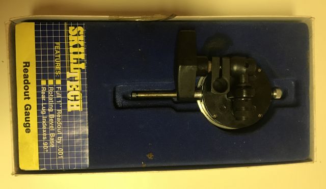
purchased some years ago for $23. the picture shows how it can be connected to a rod for vertical or horizontal mounting
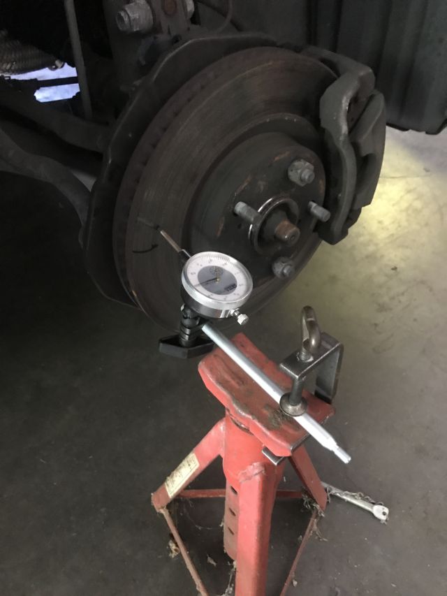
The setup (after some experimentation) is simple – I found a rod to which the gauge could attach, and I secured the rod with a clamp to an axle stand.
you can clearly see the rotor, against which the tip of the gauge is pressing and the brake caliper near the top right corner
I ensured the vehicle was safely and securely supported by an axle stand in addition to the car jack. The left rotor had no runout, which means I rotated the rotor 360 degrees and the gauge needle did not move by even a thousandth of an inch. However, the front right rotor had 4/1000″ run out. Instead of ordering a $25 rotor I splurged and ordered a $40 replacement rotor. And I removed, cleaned and greased the two caliper pins on each caliper which enable the caliper to move and center on the rotor – perhaps this is the reason why one rotor went bad – too much heating from a recalcitrant caliper.
The new rotor arrived, I installed it and the brakes are now fine.
Dishwasher machine fix
Some time ago M. informed me the dishwasher was not fully draining. Since it appeared to be otherwise ok, I ignored the issue. Then M. told me there were particles on the plates. New machine or fix the old?
Youtube has excellent videos for working on the Kenmore Elite dishwasher (model 665), which were easy to follow. Remember to first disconnect power at the breaker panel/distribution board. I used a shop vacuum to suck out the water in the sump so I could locate and remove the sump parts. I removed the detergent gunk and, following the video, located and removed the sump check valve. Except it was broken – the top half came out easily, the bottom half took a lot of fishing to locate and retrieve.
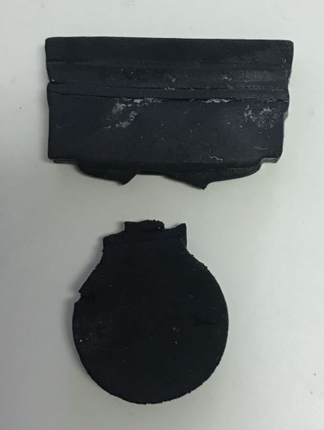
severed sump check valve. circular flapper flexes to allow pumped water out and re-seats to prevent water returning to sump
I ordered a new part (cost $14 before taxes) and installed and the old dishwasher now works ok. I believe that over time water in the sump which was not pumped out, deposited detergent sludge and so enabled the build up which became troublesome.
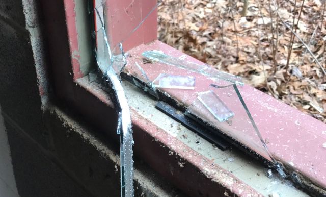
My tractor building has roll-up door on one end and a 4×5 ft window at the other end. It is insulated glass in a steel frame. And has been fine until yesterday when I backed my Case tractor with pto chipper into it, and it shattered.
Up till then I had a good morning. My bobcat started instantly and I turned the compost heap and then I chipped a lot of small trees and branches. And feeling good about everything I then reversed my chipper through the window. I designed the building to accommodate a tractor. Then because I am lazy I left the chipper attached. But even then there was 10 ft to spare. But now I also put the bobcat into the building with its bucket neatly slotted into the tractor’s bucket and a total of 3 inches to spare. But 3 inches is insufficient margin when you are tired and edging back a 9,000 lb old workhorse (Case IH 585 plus bucket plus chipper plus water filled tires).
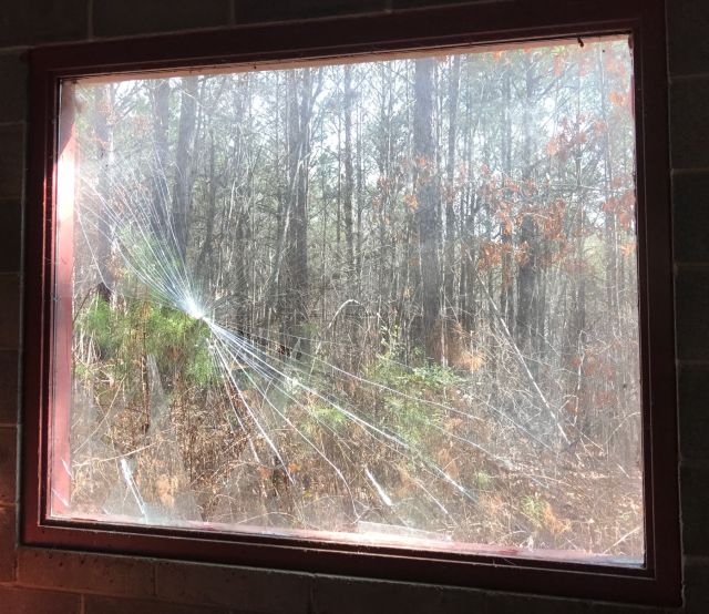
picture from outside showing steel frame. the white pipe above the window transfers rainwater from the gutter on one side of the building to the storage tank on the other side
So what to do? I have not been successful cutting glass and decided rather than do it myself to call a professional. I tried 3 local outfits which all had decent websites. I sent a pic (see above) to one and they said $589 with 50% upfront deposit. Another estimated $340 for plate glass and $370 for tempered glass, 0.25″ thick, but there was a wait of at least 2 weeks. The third estimated $365 and a 3 day wait. The 2nd and 3rd quotes did not see a pic of the window and I was concerned that their cost would be higher.
So I decided to research. What about acrylic rather than glass? I learned the pros and cons of plexiglass vs glass. Glass is cheaper, scratch resistant, easier to recycle. Plexiglass is more transparent (lets thro more light), lighter, more resistant to breaking and shattering and easier to work with. I became interested in plexiglass. An internet provider could cut plexiglass to my dimensions to .0625″ accuracy for $180. But shipping was an additional $125. I asked if I could pickup from their Atlanta location and avoid the delivery charge, but did not hear back. I web visited Lowes and HD, and HD had 4×8 ft acrylic sheet 0.25″ thick for $185. I would have to do the cutting myself. I googled how to cut plexiglass and different methods were suggested. I decided to use my circular saw with fine tooth blade and a straight edge secured with G-clamps to guide the saw.
This morning at HD I bought 4×8 ft plywood sheeting 19/32″ ($20) and the 4×8 ft acrylic 0.25″ thick sheet ($185) and a 7.25″ 140 teeth circular saw blade ($6) – all before taxes. And got to work.
First to remove the broken glass. With thick gloves and eye protection I was still disconcerted when the glass would suddenly shatter and spray. So with an 8 ft 4×4 I just smashed out the glass. Removing rusted Phillips screws, which secured steel u-channels holding glass in frame, was initially difficult. Then I figured a solution – full weight on heavy portable drill with newly inserted Phillips driver heads and quick nudges on the trigger got them turning.
you can see the spacer which separated the two panes of glass
The metal u-channels were wedged in tightly but with patience they came out and the remaining glass shards and the spacer which separated the original 2 panes of glass.
I cautiously approached the cutting of the acrylic sheet. How this one 4×8 ft 0.25″ acrylic sheet could cost $185 (before taxes) boggled my mind. Since I only had one chance to get it right, I didn’t want to mess up. The metal frame measured 48 & 1/16″ by 60 & 1/16″. The acrylic sheet was 48 & 1/16″ wide. So I pre-cut some surplus wood panel to 48″ but it didn’t fit. I know the recommendation is to deduct 1/8″ from width and length. But I also wanted room for expansion in summer. The u-channels are 0.5″ high, so with all this considered, I decided to cut to 47.75″ by 59.75″. But first I practiced on surplus plexiglass and then after lots of scratchings and calculations, I went for it. And it fitted just right.
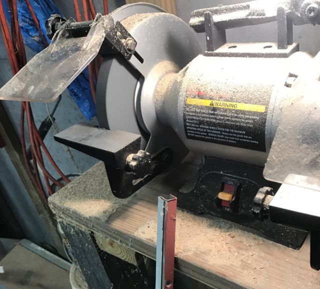
I had to ground down each end of the 4 u-channels so they could fit comfortably in the frame
However the u-channels were too tight to fit so I ground down each end on my grinder. I added some spacers between the u-channels and the acrylic. All that remains is to seal the acrylic edges with silicone and add permanent spacers. And remove all the broken glass which according to an online calculator weighs 120 lbs. Broken on Monday and replaced on Tuesday, with a significant cost saving, some satisfaction, and a more resilient solution.
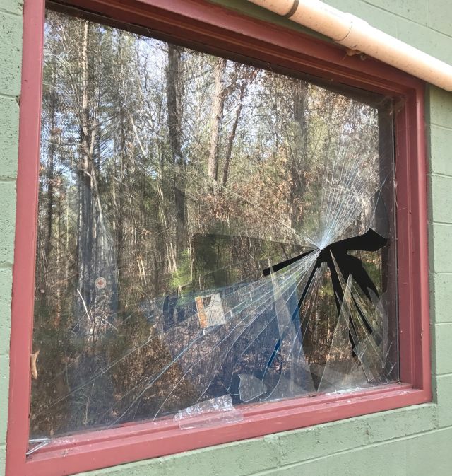
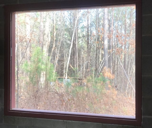
the acrylic replacement is very clear
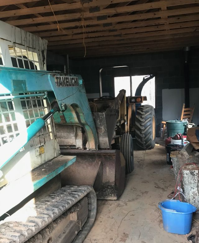
And for the time being I fitted the bobcat closer to the tractor by placing its bucket above the tractor’s bucket rather than inside it. But I will detach the pto shredder from the tractor and store it elsewhere so I have more space in the building.
you can spot the pto shredder at the rear of the tractor
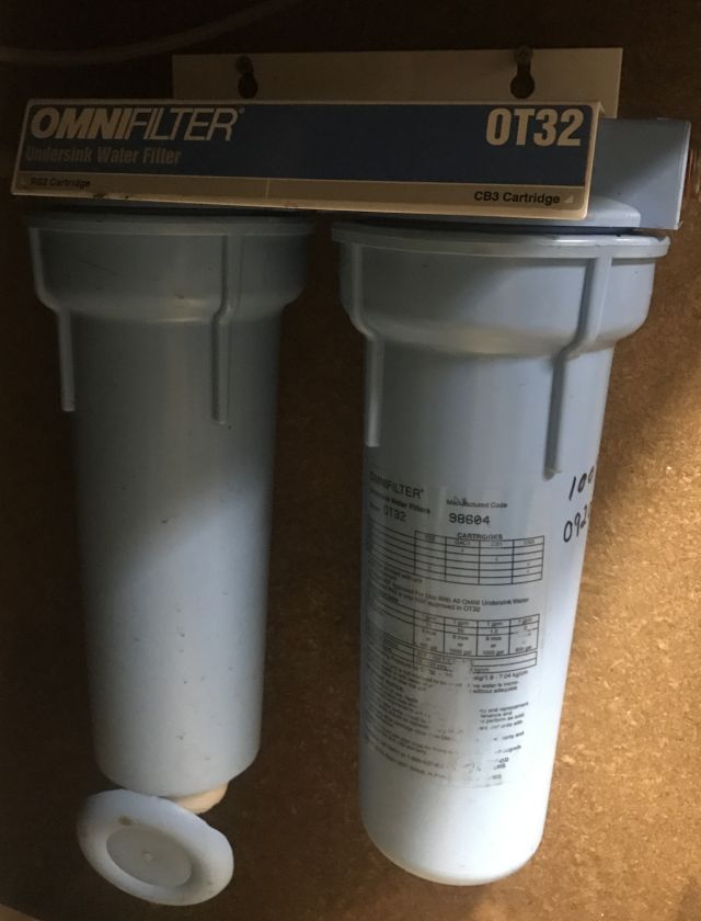
In July 1998 I installed an undersink filter. I know the date because I kept the original installation instructions. I remember the accompanying written warning but paid little attention: “To prevent costly repairs or possible water damage we strongly recommend that the housing be replaced periodically: every five years for clear tanks, and every ten years for opaque tanks. If your housing has been in use for more than the recommended period, it should be replaced immediately”.
Imagine my surprise and dismay in November 2016 when, upon returning to the house, we noticed water in the garage coming from the entrance way which leads to the kitchen, and the kitchen and most of the dining room floors covered with water. Yup, as the above picture shows, the bottom of one of the housings had separated and its failure produced a mini flood.
Busy I was with a commercial carpet cleaner vacuuming up the water on a non stop basis for several hours. Then with fans and the heaters to dry the carpets. Over the next 24 hours we were reasonably successful, except for the entrance where the underlay and the concrete floor were so wet they stayed damp and began to smell. I lifted the carpet and underlay/pad and continued heating the area until the foundation had dried. Then installed a new underlay and re-installed the carpet. So normalcy returned and we were fortunate we had carpet and tile rather than wood floors.
My communications with the manufacturers made little headway. The new housings they carried would not fit the old base so they could not offer a goodwill replacement. And they courteously reminded me of the warning to replace the housing within 10 years of installation. I could not argue.
I bought a new undersink filter with just a single cartridge. We had previously needed a 2 cartridge system but with sediment no longer an issue, a high quality chlorine eliminator filter was all that was needed. And the water bill for that month showed unusual usage of close to 1,000 gallons. So, if you have an undersink filter, remember to replace the housings timely.
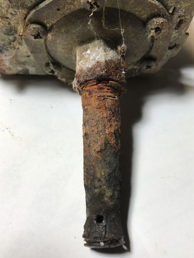
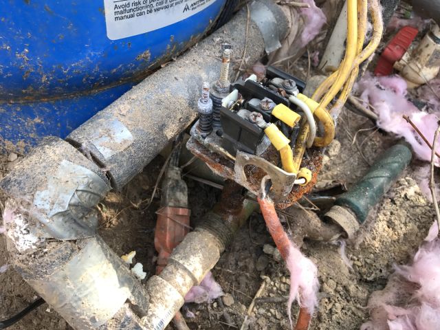
In my previous post (part 1) I describe the temporary repair I made to the expansion tank pressure switch. However the pipe/nipple connecting the pressure switch to the water manifold is badly rusted and seeping water and just a matter of time before it disintegrates.
I want the repair to proceed efficiently and so I researched how to removed broken nipples – Bob’s plumbing video (how to remove a broken pipe) was very helpful. So prior to commencing the repair I bought and assembled all the tools and parts I would need – new pressure gauge; new pressure switch set for range 30psi to 50psi; 4″ long 0.25″ diameter brass pipe; an extractor kit for broken pipes; assortment of brushes to clean threads; rust penetrant oil; and my usual assortment of standby tools. And then off to the well head.
Caution – following involves working with 240 volts and can result in serious injury or death and should not be undertaken by anyone not competent in this area.
I first switched off the power, then removed dome and pressure switch cover and photographed the wires so I could remember later which were connected to which. With a tire gauge I measured the air pressure in the expansion tank – it was 45psi. I opened a faucet and drained the water from the expansion tank. Then I looked at the nipple and, as previously mentioned, it was in bad shape.
with the switch disassembled you can see the extent of rusting of switch and nipple
After dowsing with rust penetrating oil I tried gently undoing the nipple from manifold and it turned for a bit and then broke away leaving some pipe in the hole.
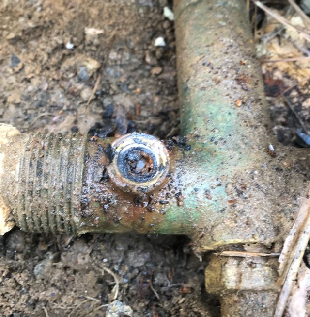
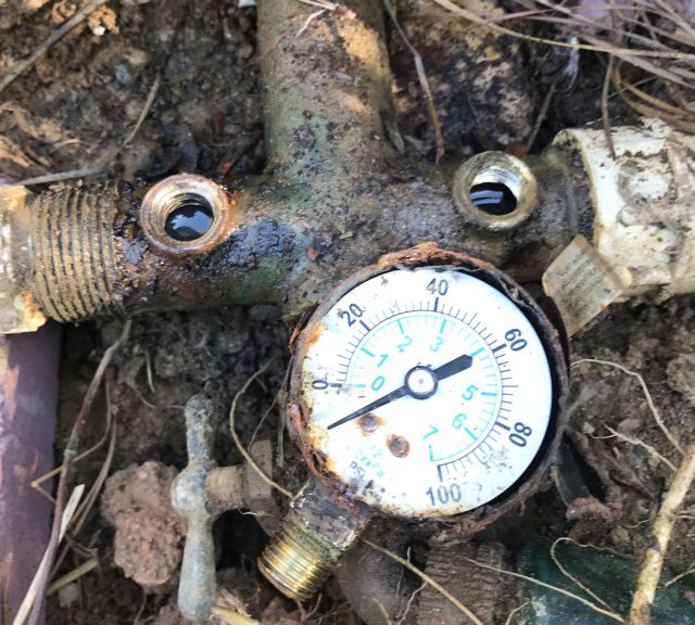
some rusted pipe remaining in whole after unscrewing the nippleyou can see the rust and small water hole and little bit of thread which unscrewed
With my nipple extractor the rest of the pipe in the hole appeared to disintegrate and I then cleaned the female threads with brass brushes. While I was at it I also removed the broken water gauge.
the 2 cleaned holes – 1 for the nipple, 1 for the gauge, and the old gauge
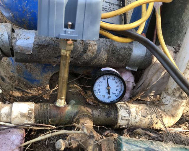
And installed a new gauge and was disconcerted to see that somehow I had cracked the glass cover. I used pipe thread sealant and connected up the new pressure switch and pressure gauge.
the new parts in place and the expansion tank charged. I will try replace the cracked glass cover of the gauge
And then switched on the power and watched the gauge rise to 50psi and heard the switch click open and stop the pump. Everything was working fine. I checked the expansion tank pressure with my tire gauge and it was 45psi. Mission accomplished.
Unexpectedly, Friday evening, no water in the house. No warning signs such as discolored water which could indicate the well was running dry. Checked the power supply board and the switch was on. Called the well repair guy and asked if any wells were running dry. He said 12 in the mountains but none at my level and he would visit Saturday 6pm.
Caution – following involves working with 240 volts and can result in serious injury or death and should not be undertaken by anyone not competent in this area.
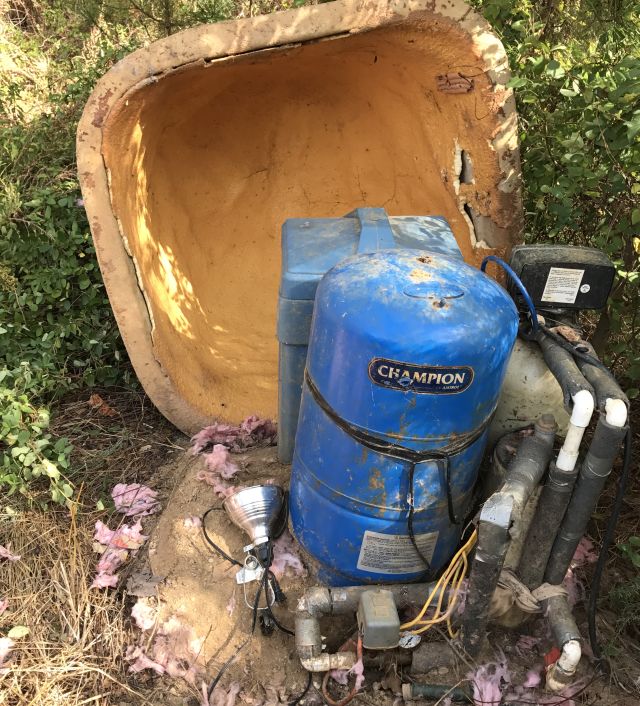
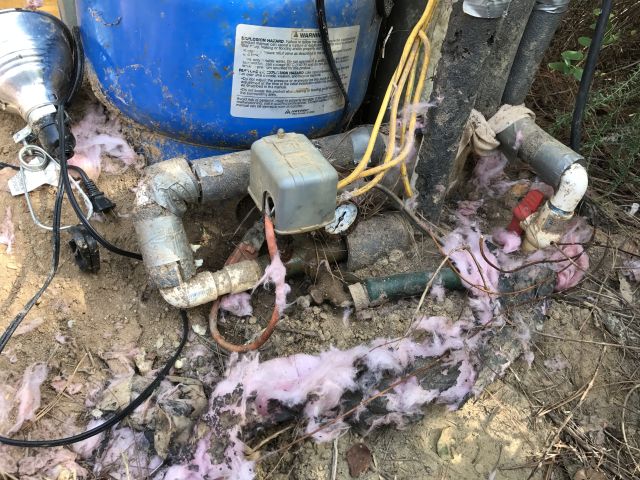
the grey box in the middle is the pressure switch for the blue expansion tank
Saturday morning I lifted the dome cover over the wellhead and removed the cover over the wires.
with cover removed wires carrying 240 volts are exposed
Yes, the wires from the house were carrying 240 volts. I then switched off the power. So what could be the problem? The well is about 400 feet deep and that’s where the pump is located. The problem could be a break in wires to pump, pump itself, water pipe from pump to surface or from wellhead to house, or worst case, a dry well. The the pump was pulled and replaced in 2007 – cost $1,200. Pumps usually last longer but ground lightning strikes can prematurely age a pump. My neighbors well ran dry a few years ago and to drill, fracture and install a new well cost around $12,000. The potential costs could be high.
The ground from wellhead to house was rock solid dry which is what you get in the extreme drought situation in north Georgia – so no leak between wellhead and house. While I was at it I walked over the septic tank and pipeline area and it was dry, so no ongoing leak in the house draining the well.
Back to the wellhead. Could there be another issue? The expansion tank for this well is located at the wellhead. The function of the expansion tank is to extend the life of the pump by holding reserve water under pressure for the house and when the water pressure in the tank falls below a set level it then switches on the pump. Typically it switches on the pump when the pressure falls to 30 psi and switches off the pump when the pressure reaches 50psi. Thus the life of the pump is extended since it does not have to cycle on and off every time water is used in the house. The expansion tank is connected to a pressure switch which is normally in the closed (on) position and it opens (cuts power off) when the expansion tank is fully charged. I looked more closely at the switch and noticed the plate which should be closed when water is needed was loose and not touching and providing continuity to the terminals (if you look carefully you will see there is no contact between the plate and the terminals).
There is a spring which holds the plate to the terminals and it must have broken and was not in sight. It seemed there were 2 ways forward – replace the entire switch or just the spring. The small pipe called a nipple, which connects the switch to the main pipe is badly corroded and I am quite sure will not come undone without disintegrating.
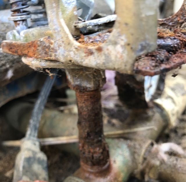
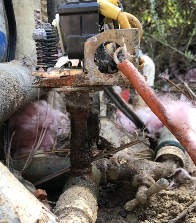
corroded pipe which joins pressure switch to water manifold. not only badly rusted but also leaking water
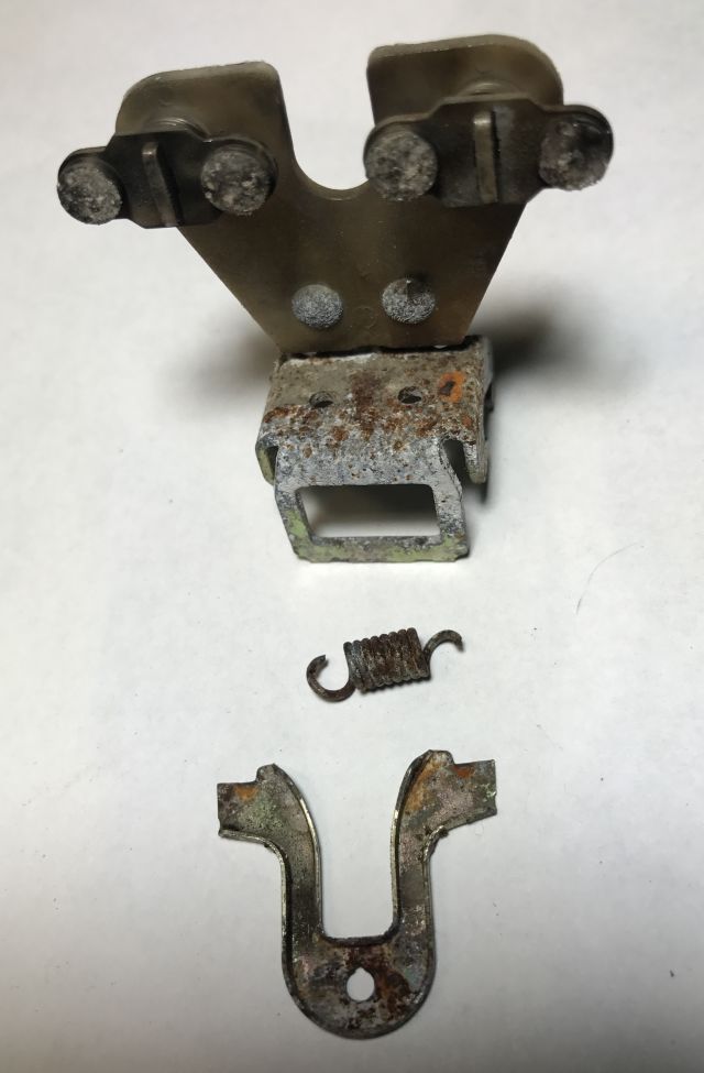
I wanted a quicker fix for the time being and decided to try replacing the spring. Fortunately I have a spare previously used switch and so I headed to my workroom and, after brewing a fresh mug of coffee, began dismantling the spare switch to figure out how to access the spring which is below several other parts, and how to re-assemble it. First attempt took about 20 mins, second attempt 10 mins, and by 4th attempt I could do it from any angle in about 5 mins. I removed the spring and some adjacent parts from the spare switch and headed back to the wellhead. And about 10 mins later the switch was repaired and I switched back on the power and the house received water and, as expected, once the expansion tank was charged, the switch snapped open.
you can see the old spring which failed (right clasp broken) & 2 other parts which I replaced as well
So the switch appears to work ok and I canceled the visit from the well repair guy, and I am now thinking how I will remove and replace the corroded pipe. See part 2.
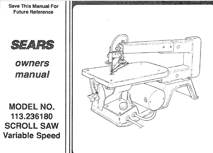
The manual is dated October ’92 so I must have purchased the scroll saw in the early 90’s. It worked fine though I did not use it much. Recently I had need for it but there was no response when I plugged it in.
Notice: If you are not competent with electricity do no attempt anything mentioned below – serious harm or death can result – instead seek professional assistance for your electrical problem.
I removed the base plate to expose the circuit board and checked: a) was power reaching the circuit board (yes); b) was the on/off switch functioning (yes); c) was there a fuse which may have shorted (no); d) was power being output to the motor (no). Conclusion – the circuit board was receiving power, no fuse had shorted, the on off switch worked fine and no power was output to the motor which drives the saw. So the motor was fine and there was a problem with the circuit board.
Elsewhere on this website I describe how I shipped circuit boards of an oven and a refrigerator to a specialist firm for repair. Also how I have replaced capacitors of air conditioning units. And how I replaced the fuse of a Bose cd/radio. But I have never repaired a circuit board. So time for a new challenge.
The beauty of old appliances is their circuit boards appear simple and are easier to work with than the modern stuff. The pcb (printed circuit board) of the Scroll Saw has relatively few components:
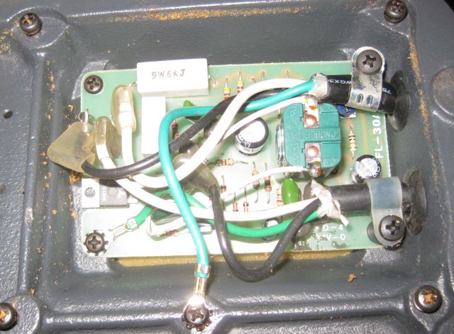
the pcb attached to the base of the saw. AC volts come in top right and DC volts go out bottom right
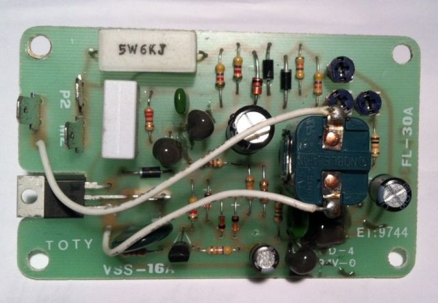
Here is a better pic with the connectors removed:
topside view -you can clearly see the components and there are not too many of them
Some pcb’s have a numbering system for each of the components – not this one. The big green device on the right is the on/off switch. The 3 barrel looking devices with the silver tops are the capacitors – there usually is a problem with one of them. Then there are a number of resistors and diodes and several transistors (some covered in glue) and on the left, just above TOTY a thyristor with 3 legs. The rectangular horizontal white object at the top is a resistor and the rectangular vertical white object is a capacitor. Plus other items such as a varistor and pots.
You will notice on bottom right a number E1?9744. I hoped to find a schematic of this pcb on the web and fruitlessly googled this number which I thought was E119744 or some other combination. To no avail. Testing and replacing components is ok but I would much rather understand how the power supply actually works. I have a 1991 Radio Shack booklet on “Building Power Supplies” (compatible lineage) which was helpful explaining the principles of PWM etc. but even then I could not figure out how this particular pcb worked.
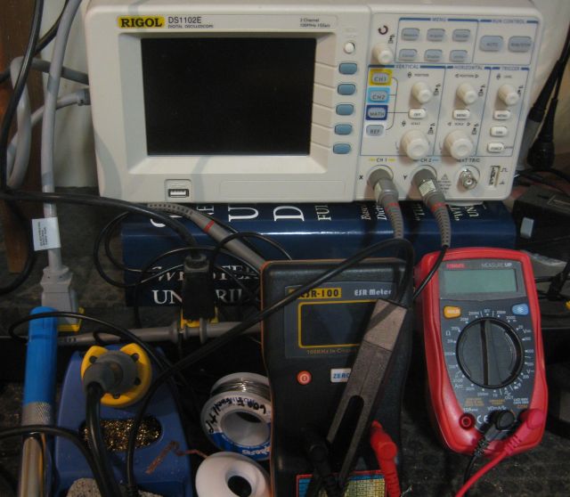
I thought the only way to test a capacitor is to unsolder and remove one of the legs from the circuit. I did this with the large cap (470 micron Farads) next to the switch, and it was fine, but what a pain for testing. Then I learned about ESR meters which can test caps seated on the pcb. Much easier. And guess what – the cap at the bottom (47 micron Farads) was defective. I placed an order for a replacement cap and got instead a 4.7 micron Farads cap. So I found an old pcb (one of my sons collected them) and unsoldered a 47 micron Farad cap and it tested fine and I installed it.
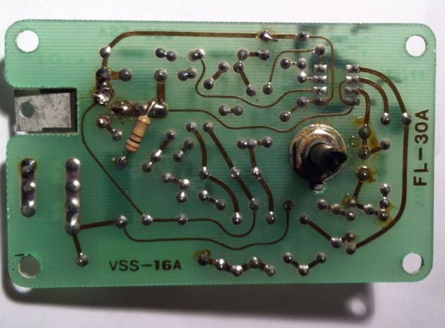
Here is an underside view of the pcb:
the object on the right is a shaft connected to the on/off switch. when pulled up it switches on the motor and when rotated it alters the speed of the motor
My next focus of interest was the thyristor the rectangular white object visible through the board cutout on the left of the picture. I surmised that the cut out was to allow the thyristor to be attached to a heat sink which would dissipate the heat generated during operation and therefore the non presence of a heat sink could have contributed to its failure. Design flaw?
From the topside view you can see the thyristor has 3 legs – a collector, emitter and base. No current flows unless voltage is applied to the base. When this occurs the thyristor should latch which means that when the voltage is removed from the base, the current continues to flow from collector to emitter. I unsoldered the thyristor and tested it and when base voltage was removed current stopped flowing from collector to emitter. It was defective. I ordered and installed a new thyristor (fortunately the defective component had sufficient information for identification).
I thought the pcb should work but it didn’t. I was stumped. I retested the components – all fine. Rather than mess with 120 VAC I connected the pcb to 24VAC – less chance of electrocution. And, unexpectedly instead of getting <1 VDC I suddenly got 16 VDC. I re-installed the pcb connected the power and, it didn’t work, back to <1VDC. A lot of head scratching and I concluded that one of my soldered joints must be faulty. Reconnected to 24VAC and gently pressed with a gloved finger each of the components – the voltmeter stayed below 1VDC. Then I pressed the thyristor and the meter showed >16VDC. Solution. On examination one of the legs was cold soldered so I resoldered it and got my >16VDS with the 24VAC supply. Reinstalled the pcb and connected to mains power and it works. The scroll saw is back in operation!
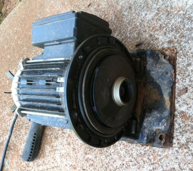
With the beginning of winter I now always ensure that I have disconnected my water pumps and drained the water. My carport pump (moves 2,400 storage gals) started fine, but my 1hp Water Ace (moves 2,800 storage gals) just made a humming sound when I tried pumping today. Another challenge!
Probably bad brushes I thought but usually there is warning – a lot of spluttering and starting in fits. Not this time and why should it fail to start after the winter break? I moved it to the workshop and removed the front end where the centrifugal impeller is – it turned with difficulty.
the pumping end -the motor spins the disc which has slits in it to catch the water and force it through the center hole
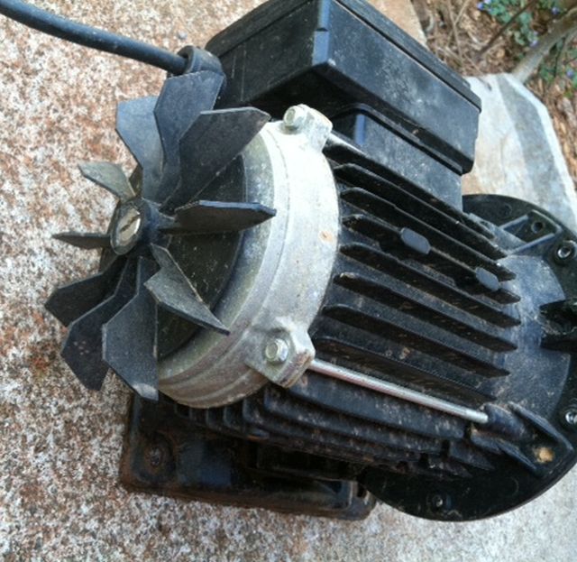
Odd, I thought something must be jammed. While it was open I removed some small stones caught in the slits. So what could it be? I happened to look at the rear end and the cover was not seated properly. Beneath the cover is the fan which is also driven by the motor.
cooling fan with cover removed
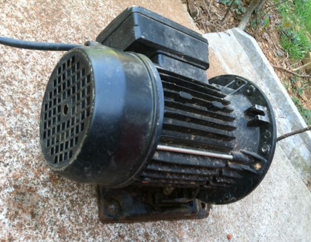
Now, with the cover removed, the impeller and the fan (they are connected to the same drive shaft) turned easily. I carefully replaced the fan cover and the front end cover and the pump started fine and pumped without leaking. All done!
pump fan cover replaced
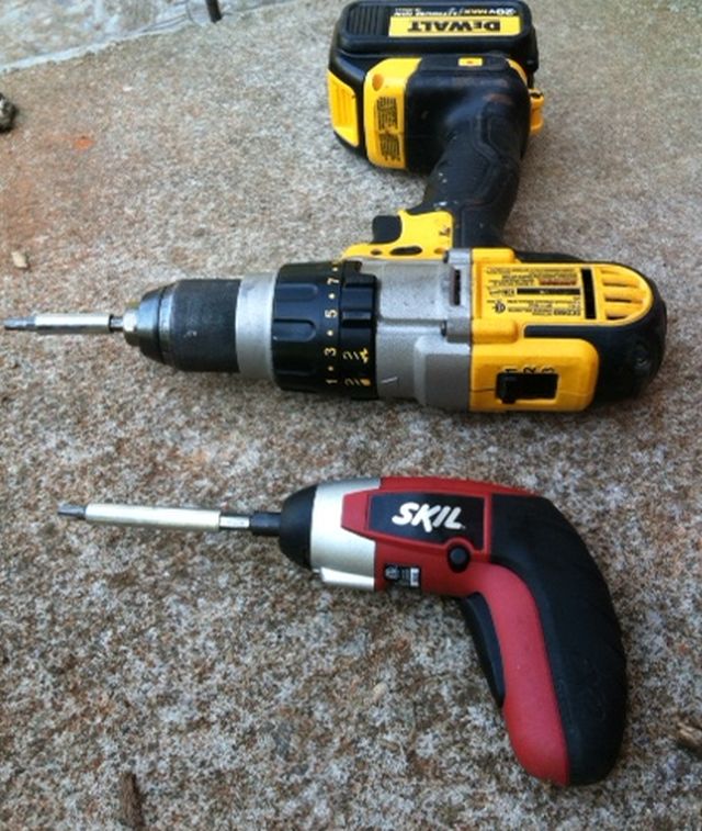
To remove the bolts I looked for my battery powered screwdriver, could not find it and so used my drill at lowest speed and torque setting. Mistake! Even at the lowest settings it is too fast and too powerful. I more determinedly looked for the powered screwdriver, found it and then removing the remaining bolts and re-assembly was fine. Moral – don’t rush.
the small powered screw driver turns more slowly and with less torque – why strip bolt heads needlessly?
My seedlings are progressing well – below is a snap of some of my tomatoes in 2″ soil blocks in the greenhouse.
some tomatoes identified with venetian blind plastic strips
A senior credit manager once told me: “Catch me once, shame on you, catch me twice, shame on me.” Which may be fine in the world of relationships but for the consumer in this information filled internet world the maxim should be: “Catch me once, shame on me!” Last week 2 incidents when I was almost caught and by “caught” I mean taken advantage of.
Ever since I rebuilt my Troy Bilt chipper shredder engine (model # 47330) in August 2013- see post on seized engine repair it has performed flawlessly. Except that prior to the seizure the gas tank leaked when filled>50% and I solved this my keeping gas levels down until it began leaking at the bottom where the fuel hose is and stank out the garage. I did my research and the cheapest replacement for the same tank was $76 ouch! for a plastic 4 qt fuel tank! But I bought it because fuel on your hands and vapor in the air is not good and complaints were mounting. I could have cobbled something together with another fuel tank but didn’t want to mess with it. That was the cheapest price new and it fitted perfectly and quickly and was done. And I wasn’t caught – a vendor can charge whatever and the consumer can buy or not buy.
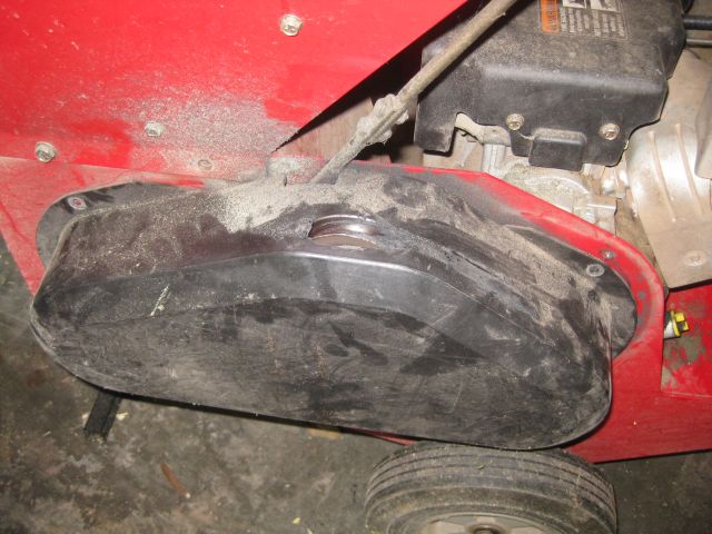
I was chipping the remains of a poplar tree – soft wood and easy going, and noticed the chipper was not as chipper (sorry – cheerful) as usual. When using equipment, if something ails, I now investigate early. The drive belt had stretched with use and the top pulley was carving a hole through the cover creating a lot of heat and slowing the engine down.
at the top of the cover you can see the hole carved by the pulley
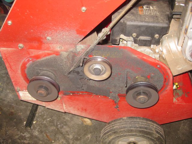
Below is shown the arrangement of the pulleys. The right pulley is the drive pulley connected to the engine, the left pulley turns the shredder/chipper mechanism and the top pulley is spring loaded and takes up the slack as the belt lengthens.
3 pulleys – the top, spring loaded pulley carved the hole in the cover
I input the model # and located the part # and googled it and found prices for a new 38″ belt ranging north of $25, delivered. Seemed a lot for a belt? So I googled some more and a helpful poster in response to a question on the belt, said Gates V-Belt #6838 was an acceptable replacement. Per belt specs, outside circumference was 38″ and outside circumference of my used belt was 40″, which made sense since my belt had stretched. The width of the new belt was 0.5″ which corresponded to my belt. My favorite auto store wanted $15.99 and WalMart advertised for $11.17. I visited the local WalMart, where I buy my oil and filters, and discovered it does not carry belts. The big internet retailer “A” offered the part for $11.17 (after tax $11.95) and I ordered using my prime account with delivery in 2 days. My point is that a lot of manufacturers use standard parts. If you buy the part using the manufacturers part # it will often cost more than if you can locate the standard part’s part #. This may void the warranty but for me, with my old, old equipment this is not an issue. And Gates is a well known belt manufacturer so the quality of the replacement is not an issue either.
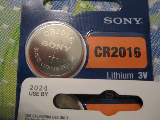
The second situation was the remote car key was not working. The car is 8 years old and I replaced the key just a couple years ago. CR2016 is the battery #. The local Publix carries watch batteries but was out. The local Kroger doesn’t. We are mid 90’s now in Georgia and this was getting frustrating. I visited the local shoe repair store to have my favorite shoes repaired. My better half said this was ridiculous, I should just buy a new pair. And then a recent WSJ article 060315 said having good shoes repaired was sound strategy. So I felt good with this endorsement and while in the store noticed it had a watch repair section. I asked the guy behind the counter if he carried this battery. He found a battery and as to price said $10. Noting my reaction, he said $10 was when he replaced the battery in a watch and for just the battery – $7. Now I want to support the small guy but $7 is too much. As I headed for the door he said $5.
So back to the big internet retailer “A”, where some diligence was needed. Lots of CR2016 battery suppliers but how many came in shrink wrapped, date stamped packs? Apparently the life should be around 10 years and I figure the reason the last replacement faded after 2 years was it might have been old stock to start with. (I did not check for a date when I purchased it). So I ordered a Sony 20 piece, blister packed and apparently date stamped package, from a high rated supplier for $8.40 with 2 day delivery. I would have been happy to pay $3 for a battery but $7 was being caught and I was not in the desert desperate for water.
the new battery, date stamped 2024! from a well known manufacturer!
At this point you may be saying – “much ado about nothing, what’s in a few dollars?” So a snippet from last Saturday’s run at the river where we are training, sort of, for the July 4, 10k in Atlanta, which is the largest attended 10k in the world. My buddy “Jack” a former engineer now retired, objected when I said there was minimal inflation today. A few days earlier a new capacitor for the outside compressor unit of his a/c cost him $190. I asked if that included the labor and Jack said with labor included, the cost was $350. I mentioned I had replaced several caps on outdoor compressors and each one cost <$30. To which Jack said they just got back from a trip, temps were in the 90’s and wife insisted on an immediate repair. Which is fine but the price of caps has not increased, though the cost of an emergency repair may well have. My point is, if you can make repairs safely (and this is a big IF) then watch the pennies and the dollars will take care of themselves.