Space Invaders and the world of 1’s and 0’s

After leaving South Africa in the late 70’s I worked in London for one of the “big 8” accounting firms, now called the “big 4”.  I remember a multi-day training event where in the evenings we drank a lot of beer, socialized and I discovered the addictive Space Invaders arcade video game which was housed in a large console.  As the commander of the only remaining space ship I had to dodge from side to side to evade incoming missiles and simultaneously destroy the horde of menacing invaders which moved across the screen left to right and lower and lower, and faster and faster all the while to a heart thumping hypnotizing background sound.

I have now completed a 16 week embedded systems IoT (Internet of Things) course with University of Texas, Austin, which was excellent, and one of the last projects was to write the software for Space Invaders and build the hardware. 

inputs and outputs

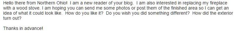
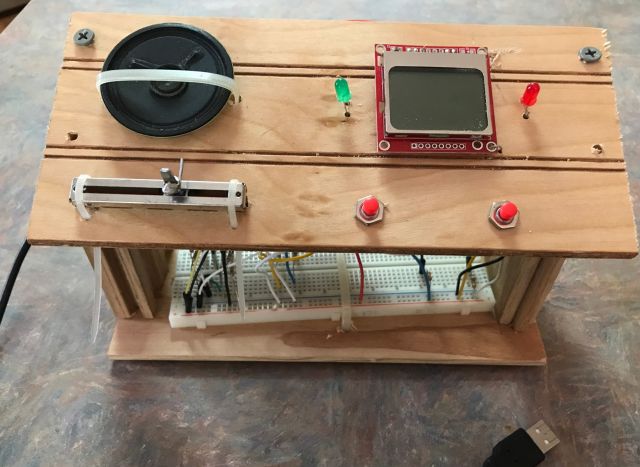
Above are the inputs and outputs.  The inputs are the slidepot (bottom left) which moves the defender ship horizontally across the screen and the 2 red buttons which are the fire buttons – one fires vertical take off missiles, the other 2 diagonally veering missiles. 

The outputs are the speaker which transmits battle sounds, the LCD screen which shows the field of combat with invaders moving across the sky lower and lower and exchange of missiles and explosions; and 2 signal lights – the green shows success, the red shows failure.

this Cortex TM4C microcontroller is the brains behind the scenes.  we used this powerful device throughout the course

My game software is relatively simple – I do not have levels to attain and the enemy does not move faster as the game progresses.  If my space ship is destroyed then I lose, if the enemy invaders or “sprites” are destroyed first, then I win.  Here is a YouTube video of my software in action – https://www.youtube.com/watch?v=Zok8T3PWSEE

We used to inhabit an analog world where even our record players and film cameras were analog with the film directly capturing the nuances of the image, and the groove in the record directly transmitting to the pickup stylus the recorded sounds of voice and music.  Now the digital world of 1’s and 0’s intermediates – sound is converted to binary digital sound and images to digital images.  And when we hear the sound through a speaker or headphone it has been converted back to analog sound. 

In the Space Invader game, ADC (analog to digital converter) software is used to convert the movement of the slide pot (which is analog) into a digital signal and DAC (digital to analog converter) is used to convert the sounds of the invaders, the missiles and explosions from digital code to analog output for the speaker.  (It is clever how the invaders are coded to advance digitally across the screen and I would explain the principles except that I will lose most all the readers who have persevered to this point.)

We immerse ourselves increasingly in the digital world for information, socializing, entertainment and transactions.  First the CD players, then the internet, now smart phones and soon more of us will fall under the spell of AR (augmented reality) and VR (virtual reality).

Through VR we will be able to visit world heritage sites and see animals and birds and fish more vividly than we could possibly do in the wild.  But will it be a satisfying experience?  Can there be satisfaction when instead of a strenuous hike, pestered by mosquitoes, to see an isolated waterfall, we ask our digital assistant for the Victoria Falls (the Smoke that Thunders) or the Niagara Falls and we zoom in to all their splendor. 

The world of 1’s and 0’s will enhance our safety (house security & car sensors) and health (personal monitoring sensors, data compilation & analysis) and efficiency.  But for me it has limits and working in the field and growing food is far more satisfying than working out in a gym accompanied by sound and video generated from 1’s and 0’s.  For me live guitar music or theater or a local sport event is more satisfying (most of the time) than the best guitarist, actors or sports heroes, recorded in video? 

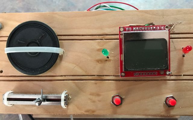
Ps1 – the edX Austin MOOC uses the ARM Cortex processor and is challenging unless you are a competent programmer.  There are easier courses and I just started a Coursera course on Arduino hosted by MIPT (Moscow Institute of Physics and Technology) which is for beginners and is fun.

Ps2 – the ADC (analog digital converter) uses successive approximation to discover the unknown analog input and convert it to binary number.  The technique is similar to the process used in a game where a friend imagines a number between (say) 0 and 255 and you have to determine the number and your friend will only tell you if the answer is higher or lower than your guessed number.  So You guess 128 (half of 256); Friend says lower. You guess 64 (half of 128); Friend says lower.  You guess 32; Friend says lower.  You guess 16, Friend says higher.  You guess 24; Friend says higher. You guess 28; Friend says higher. You guess 30; Friend says lower.  You say 29 and friend says that is the answer.  The software follows a similar technique and codes “higher” with a 1 and “lower” with a 0, and at the end of it all has determined the analog number and translated it into 1’s and 0’s. 

cracked iPhone 4 screen replacement

This morning’s wsj 6/21/17 first page article says “Bust Your Phone Again?  These Teens Are Here To Help”.  A 16 year old Nantucket resident instead of surfing, made close to $24k last summer repairing smart phones and is busy again this summer.  His charge to repair a cracked iPhone 7 Plus is $189.99.  

M. dropped her iPhone 4 last week and the screen is hard to read – see pic above.  She wants to wait for the new iPhone due later this year.  So I suggested I would try repair it.  On the internet retail giant’s website we ordered a kit comprising new screen and repair tool kit for approximately $17 plus tax.  The iPhone 4 is an old phone so replacement parts are reasonably priced.  Our phone is a Verizon phone which is different from AT&T, so it was important to order the right screen and also to follow YouTube instructions for the Verizon/Sprint phone not the AT&T. 

The kit arrived and following the excellent tutorial I began dismantling the phone.  There are lots of tiny screws and to keep track I followed a suggestion to sketch an outline of the phone and tape the screws and parts to the location where they belonged.

the easy part – removing the back cover. you can see the 2 torx screws taped below the back cover

I quickly encountered a problem – the Phillips screwdriver provided with the kit was not up to the task.  So I stalled for a day and visited a computer store to inspect their screwdrivers.  The size I needed was a Phillips PH000 and there were lots to choose from.  I settled for a kit made in Taiwan made of chrome-molybdenum, described as professional, with an ISO certification.  Perhaps all these plugs would help.  And they did – no more problems with screws.  And then I stalled again until I read this morning’s wsj article and, fired up, I resumed.

To get to the screen a whole lot of parts have to be disassembled.  Not for those faint of heart, or with unsteady hands or blurring close up vision or impatient to get the job done.  I could tick some of these boxes.

the guts have been removed and down to releasing the screen from the frame

A hair dryer was conscripted to soften adhesive and then the old cracked screen was off and the new screen installed.  On the re-assembly road back I was too confident and went too quickly and missed a few steps and had to backtrack, which was frustrating.  But eventually all the components were in place and the critical moment arrived – would it power on and make and receive a call, and it did.

the new screen has a white border, the old a black. but M. is not complaining and is almost adulatory

water heater expansion tank

In addition to my place north of Atlanta where I spend most of my time, we have a large house in Atlanta which we will sell when M. stops working.  I have begun readying the Atlanta house for sale.  It has two water heaters and neither has an expansion tank.  The code requires an expansion tank be installed if a new heater is installed or if a backflow preventer (check or one way valve) is installed.  

A backflow preventer prevents water on the house side of the device from flowing back into the main supply.  Since the house side is sealed (until you open a faucet) when water expands (from being heated by the water heater) it has nowhere to go and the pressure build up could damage appliances such as the water heater.  Therefore the need for a device which can accommodate the expansion of the water.  An expansion tank should not be confused with a T&P (temperature and pressure valve) which is attached to water heaters and releases water when the pressure is unusually high.

Expansion tanks are usually connected to the cold water inlet to the water heater.  The tank has an air bladder/diaphragm  and air valve which looks like the valve on car tires.  Instructions suggest inflating the bladder to the pressure of the water in the house.  The size of the expansion tank depends on the size of the water heater.  Our water heater is 50 gallons and a 2 gallon expansion tank cost $40 is adequate.

The question is where to add the tee for the tank. 

One suggestion was on the 90 degree bend where the tank would have the most support, but this requires unsoldering the elbow and then either re-soldering or scrupulously cleaning the existing  pipes to accommodate a SharkBite or GatorBite fitting  (“shark fitting”).  The easiest was between the 2 elbows and I ascertained there was sufficient room to pull the pipes apart to accept a new tee fitting.  Next question was to solder or use a gator fitting?  A soldered joint is rigid and regarded as permanent and once soldered can hold the tank in a vertical position.  A shark fitting can be swiveled which is convenient at times but cannot hold a tank vertical since the slightest nudge will cause it to swivel down.

I have done lots of soldering in the past.  Solder fittings are much cheaper than shark fittings and are permanent.  However, shark fittings are very easy to use and easy to undo such as when you have to replace the water heater.  There is a nagging concern that a shark fitting can come undone when I am away from the house, but the literature and others assure me this will not happen.  So I bit the bullet and used a shark tee fitting and developed a method to ensure the expansion tank stayed vertical.

Steel cable is secured around the middle of the tank.  A turnbuckle is attached to the cable and to an anchor on a wood plate which is screwed into a stud. 

the wood board has screws on the right vertical edge going to the stud. the eye of the turnbuckle is secured by a copper strap screwed to the board

By adjusting the turnbuckle I can assure the tank is vertical. 

a close up of the cable securing the expansion tank. I used one clamp for a tight hold on the tank and another clamp to provide a loop to secure the eye of the turnbuckle

I did solder the 3/4″ male fitting which is coupled to the male fitting on the tank.  I happened to have a 3/4″ male and coupler available, otherwise I would have simply purchased a 3/4″ female fitting.  If I had simply soldered the tee fitting I could have dispensed with the cable, turnbuckle and other bits shown above.

And shown below is the expansion tank on the 2nd water heater.

I reduced the space between the wall and the tank by using a right angle bracket and therefore could use a smaller and cheaper turnbuckle

brake shimmy and a dishwasher fix

When not using the truck to transport materials, I use M’s 2007 Camry which now has 155k miles.  It is more comfortable and uses less gas.  Apart from regular maintenance it has required little extra expenditures – new front rotors @ 98k; new upper engine mount @ 138k; new alternator @141k. 

But for some time brake vibration has been an issue- the brake pedal pulsates and the steering wheel shakes when I forcefully apply the brakes.  Because the steering wheel shakes this indicates the problem is the front rotors and I had replaced both rotors at 98k.   I decided that rather than again replace both rotors (new ones cost about $25 each), I would identify which was the problem and try determine why this was re-occurring.

The brake rotor, also known as the disc, (therefore the term “disc brakes”), is mounted just inside the wheel and rotates with the wheel.  The rotor rotates between 2 brake pads held in place by a caliper and braking occurs when the piston in the caliper applies pressure to one of the pads.  Since the caliper can move laterally (but not with the rotation of the rotor) the pressure is effectively applied evenly to both pads, which engage the rotor and slow its rotation and vehicle movement.  The vibration occurs because there is variation in the face of the rotor on one or both of its sides.  This is called runout and for lighter vehicles such as the Camry,  runout should not exceed a few thousandths of an inch.

I have a read out gauge -see above and below pictures.

purchased some years ago for $23. the picture shows how it can be connected to a rod for vertical or horizontal mounting

The setup (after some experimentation) is simple – I found a rod to which the gauge could attach, and I secured the rod with a clamp to an axle stand.

you can clearly see the rotor, against which the tip of the gauge is pressing and the brake caliper near the top right corner

I ensured the vehicle was safely and securely supported by an axle stand in addition to the car jack.  The left rotor had no runout, which means I rotated the rotor 360 degrees and the gauge needle did not move by even a thousandth of an inch.  However, the front right rotor had 4/1000″ run out.  Instead of ordering a $25 rotor I splurged and ordered a $40 replacement rotor.  And I removed, cleaned and greased the two caliper pins on each caliper which enable the caliper to move and center on the rotor – perhaps this is the reason why one rotor went bad – too much heating from a recalcitrant caliper.

The new rotor arrived, I installed it and the brakes are now fine.

Dishwasher machine fix

Some time ago M. informed me the dishwasher was not fully draining.  Since it appeared to be otherwise ok, I ignored the issue.  Then M. told me there were particles on the plates.  New machine or fix the old? 

Youtube has excellent videos for working on the Kenmore Elite dishwasher (model 665), which were easy to follow.  Remember to first disconnect power at the breaker panel/distribution board.  I used a shop vacuum to suck out the water in the sump so I could locate and remove the sump parts.  I removed the detergent gunk and, following the video, located and removed the sump check valve.  Except it was broken – the top half came out easily, the bottom half took a lot of fishing to locate and retrieve.

severed sump check valve. circular flapper flexes to allow pumped water out and re-seats to prevent water returning to sump

I ordered a new part (cost $14 before taxes) and installed and the old dishwasher now works ok.  I believe that over time water in the sump which was not pumped out, deposited detergent sludge and so enabled the build up which became troublesome.

wood chipper repair

I extend the life of appliances so they can age gracefully as I am also attempting to do.  But they need attention and repair.  I previously posted how I repaired (or had someone repair) the circuit boards of the wall oven, fridge and treadmill all of which are >15 years old and still work fine.  In August 2013 I posted how I rebuilt the engine of my chipper/shredder (see picture above) after the oil plug came off, the oil escaped and the engine seized.  I believe I bought the chipper new in the 90’s and have used it regularly.  Other than the engine repair, I also replaced the fuel tank (costly part), the drive belt, and the axle bearing.

I heard loud thunking from the chipper this week and noticed that the axle bearing was broken and again needed replacement after some 10 year’s use. 

you can see the damaged bearing and the end of the axle which rotates the chipper and the shredder and needs a heavy duty bearing to service it.  some debris has pierced the bearing brace and replacement is long overdue

What I refer to as the “bearing” is actually 2 components – a housing, and a bearing inserted into the housing.

with heavy hammer and steel chisel I was able to dislocate the bearing and you see it edgewise in the housing

When I last replaced the assembly some 10 years ago I am sure the price was <$20.  Today the price >$60 on all the websites I visited.  Seems a lot.  To find lower prices it helps to use a generic sku (part #) and not the manufacturer’s sku.  I had no success.  But it occurred to me that since the housing was ok, why not just buy the bearing separately?

By magnifying the website picture of the >$60 replacement assembly I was able to identify most of the part number of the bearing.  And by googling various combinations of the number I located the standalone bearing (Timken RA100RRB wheel bearing) and on Amazon prime it was available (including tax) for $17.19.  It arrived a couple days later and matched the defective bearing.

old bearing and new bearing side by side

However, I could not press the bearing into the housing.  Youtube guidance suggested I freeze the bearing and heat the housing.  Just freezing didn’t work and I was under increasing pressure from M. to chip the accumulating pile of branches and to “”just pay the $65 and get the right part”.  So I put pride aside and visited the local tractor dealer and they fitted the 2 together, and refused payment.  With hindsight I realize I was using the wrong technique.  Instead of trying to align the bearing with the housing and then force the bearing into the housing, I should have forced it in edgewise and then rotated it.  My lesson for next time. 

new bearing in old housing installed on chipper.  you can also see the fuel tank I replaced a few years ago, since the old one leaked at the horizontal seam

It was quick work to reinstall the bearing on the chipper and today I chipped >2 hours and the new bearing appears fine.  I should mention this is the chipper I use at the Atlanta house.  North of Atlanta where I have my growing operations I use a large chipper driven by the PTO of my 60hp Case 585 tractor.

fence repair the easier way

Some time ago I noticed  the perimeter fence was down – a post had rotted at the base and 2 8ft attached panels fell with it.

you can see post rotted at base and 2 attached panels.  also notice left standing post has warped and panel has separated

I call them panels because you can buy them that way – 8 ft length with 3 horizontals and 17 attached panels for about $49.  Or you can buy 3 2×4 8ft pieces for horizontals and 17 individual panels and nail them together.  I prefer the latter – easier to transport and move and cheaper but will take much longer unless you have a nail gun, which I happen to have.

But before considering the panels I had to first figure how to replace the post.  I confirmed its base was concreted into the ground and assumed the rot was because the fence is at the bottom of a hill and soil carried down by the rain covered the post for about 3 inches above the concrete base preventing quick evaporation of rainwater.

One option was to pull out the stump and the concrete base, which would be hard work, take some time and leave a big hole requiring a big plug of new concrete and rocks.  Another concern was I would have to locate the post just right so that each panel could be attached to it.  A post is about 3.5″ wide and since the panels touched each other when in place, each would have to extend across the post by 1.75″.  Too finicky.  Especially if the panels were no longer vertical.


a sketch of the problem

So instead I decided to install a new post on either side of the concrete plug gripping the rotted post.  Advantages:  1) save a lot of work pulling out the old post; 2) would be twice as strong; 3) much easier for attachment of panels since each panel would have its own post rather than sharing a common post.

a sketch of the solution, the old concrete base contributes to holding the new bases in position

I had 2 unused 8ft posts available – each sunk 2ft into the ground but not concreted.  By pushing and pulling I could have loosened and wiggled them out but why risk the back when I have a farm jack.  With a slip hook on a chain it hauled them out of the ground easily and quickly.

this farm jack which I bought some years ago at a discount store and frequently used has proved its value

Installing the new posts was relatively easy – in addition to the clam shell post hole digger I used a long crow bar for breaking through hard patches and old saw for roots.  And I made sure to concrete above ground level with a bevel to direct water away from the post.  I bolted the panels to the replacement posts to better secure them.  And it was done.

I didn’t mention my sudden motivation to repair the fence.  The fence is an outer perimeter fence and there is an inner perimeter fence and 10ft inside the latter is one of my bee hive locations.  It is shielded from the setting sun by an apple tree and from the north west wind by a glass window I purchased for a few dollars at the thrift store.  Just recently I noticed the window had been shattered either by a catapult or bb gun or maybe .22 – I mention all 3 since in a couple of spots only one of the double windows was broken and in others the projectile penetrated both windows and the frame.

the bee hive was fortuitously located elsewhere or I might have had to also deal with a toppled bee hive

  Made me think of the strategy of Giuliani, former mayor of New York City – if there are a few broken windows more will be broken.  If they are all fixed likelihood of vandalism much reduced.  So the 2 downed panels gave an aura of neglect and repair was necessary.

my wood stove

I was thinking just a few days ago, when winter abruptly descended, how efficient and useful my wood stove has been.  Over the past 3 winters it has lived up to all my expectations and provides sufficient heat for the house except in the evening before retiring when we use supplementary heat to warm the bathroom.  Coincidentally, I received an email with some questions on the wood stove (see below):

Here are some thoughts.  But first, if you are interested in the topic do read my posts, parts 1 & 2 titled “wood stove installation” dated March 2, 2014.  You can easily locate them by going to the search box and entering “wood stove”.  Part 2 ended with a functioning wood stove and gaping hole in the wall.  In my post dated July 27, 2014 (also easily located via the search box) I describe how I completed the job and include a picture of the finished product which you can also see in the picture above.

Fuel

I use wood salvaged from downed trees and my first choice is oak though I will use other hardwoods if necessary.  I never use pine for fuel, instead I add it to my contour ditches to decompose and enrich the soil.  I have a decent chainsaw and electric chain sharpener (never got the hang of doing it with a file)  and I split the wood with a maul wearing eye protection.  Splitting is generally easy unless there are knots and then it becomes a challenge and a puzzle to figure the solution.  Only once have I had to chainsaw an invincible knot infested log.  I generally cut the logs to the length of the firebox.  A few inches too long can be accommodated by inserting diagonally.  The logs in the picture below were cut in the early days and are too short.

satisfying to split firewood, takes practice to deliver the blow repeatedly at the same spot, and takes experience and luck to thwart a knot

I keep all my firewood under cover.  Beats me why  neighbors leave theirs uncovered when a tarp would make such a difference.

Smoking

Smoking is when smoke enters the room, usually when I am starting the fire or when I add fuel.  Both are easily avoided.  Before building the fire I take a single double page of newspaper and twist it as if wringing a towel and I light both ends and place at the back of the firebox in a U position.  The flames heat the flue and this will entice the smoke from the fire to go up the flue.  And when adding wood you just have to remember to open the door slowly so as n0t to distract the smoke from its journey to the flue.

Lighting

Lighting the fire has not been a challenge.  I use a short piece of duraflame quickstart – the packaging says it is “made with wax and a blend of recycled and renewable biomass fibers” and it gets the fire going.  If the wood is wet it will “smoke” as it releases moisture.  In the beginning when this was a problem I used scraps of 2×4’s (untreated) to augment the firing process.  Now all my wood has had time enough to dry.  Although not sanctioned by the manual I leave the door slightly ajar (but latched) and this boosts the firing process and when the fire has achieved momentum I lock it down.

My wood stove does not have a blower , though it is available as an option.  So to circulate the heat I use the ceiling fan, and it works well enough.

And finally, never place anything on the stove to dry.  You turn your back and you have an open fire in the living room!   Oh, I forgot, the chimney installer recommended cleaning/sweeping the chimney at least annually – which is not as difficult as with a fabricated fireplace.  You just access the chimney from the rear (see my pics in earlier post) and remove the cap at the tee and with rods and a brush snare the soot in a garbage bag.  And the wood ash and the soot go into my vegetable growing beds or compost heap. 

replacing a glass window

My tractor building has roll-up door on one end and a 4×5 ft window at the other end.  It is insulated glass in a steel frame.  And has been fine until yesterday when I backed my Case tractor with pto chipper into it, and it shattered.

Up till then I had a good morning.  My bobcat started instantly and I turned the compost heap and then I chipped a lot of small trees and branches.  And feeling good about everything I then reversed my chipper through the window.  I designed the building to accommodate a tractor.  Then because I am lazy I left the chipper attached.  But even then there was 10 ft to spare. But now I also put the bobcat into the building with its bucket neatly slotted into the tractor’s bucket and a total of 3 inches to spare.  But 3 inches is insufficient margin when you are tired and edging back  a 9,000 lb old workhorse (Case IH 585 plus bucket plus chipper plus water filled tires).

picture from outside showing steel frame.  the white pipe above the window transfers rainwater from the gutter on one side of the building to the storage tank on the other side

So what to do?  I have not been successful cutting glass and decided rather than do it myself to call a professional.  I tried 3 local outfits which all had decent websites.  I sent a pic (see above) to one and they said $589 with 50% upfront deposit.  Another estimated $340 for plate glass and $370 for tempered glass, 0.25″ thick, but there was a wait of at least 2 weeks.   The third estimated $365 and a 3 day wait.  The 2nd and 3rd quotes did not see a pic of the window and I was concerned that their cost would be higher.

So I decided to research.  What about acrylic rather than glass?  I learned the pros and cons of plexiglass vs glass.  Glass is cheaper, scratch resistant, easier to recycle.  Plexiglass is more transparent (lets thro more light), lighter, more resistant to breaking and shattering and easier to work with.  I became interested in plexiglass.  An internet provider could cut plexiglass to my dimensions to .0625″ accuracy for $180.  But shipping was an additional $125.  I asked if I could pickup from their Atlanta location and avoid the delivery charge, but did not hear back.  I web visited Lowes and HD,  and HD had 4×8 ft acrylic sheet 0.25″ thick for $185.  I would have to do the cutting myself.  I googled how to cut plexiglass and different methods were suggested.  I decided to use my circular saw with fine tooth blade and a straight edge secured with G-clamps to guide the saw.

This morning at HD I bought 4×8 ft plywood sheeting 19/32″ ($20) and the 4×8 ft acrylic 0.25″ thick sheet ($185) and a 7.25″ 140 teeth circular saw blade ($6) – all before taxes.  And got to work.

First to remove the broken glass.  With thick gloves and eye protection I was still disconcerted when the glass would suddenly shatter and spray.  So with an 8 ft 4×4 I just smashed out the glass.  Removing rusted Phillips screws, which secured steel u-channels holding glass in frame, was initially difficult.  Then I figured a solution – full weight on heavy portable drill with newly inserted Phillips driver heads and quick nudges on the trigger got them turning.

you can see the spacer which separated the two panes of glass

The metal u-channels were wedged in tightly but with patience they came out and the remaining glass shards and the spacer which separated the original 2 panes of glass.

I cautiously approached the cutting of the acrylic sheet.  How this one 4×8 ft 0.25″ acrylic sheet could cost $185 (before taxes) boggled my mind.  Since I only had one chance to get it right, I didn’t want to mess up.  The metal frame measured 48 & 1/16″ by 60 & 1/16″.  The acrylic sheet was 48 & 1/16″ wide.  So I pre-cut some surplus wood panel to 48″ but it didn’t fit.  I know the recommendation is to deduct 1/8″ from width and length.  But I also wanted room for expansion in summer.  The u-channels are 0.5″ high, so with all this considered, I decided to cut to 47.75″ by 59.75″.  But first I practiced on surplus plexiglass and then after lots of scratchings and calculations, I went for it.  And it fitted just right. 

I had to ground down each end of the 4 u-channels so they could fit comfortably in the frame

However the u-channels were too tight to fit so I ground down each end on my grinder.  I added some spacers between the u-channels and the acrylic.  All that remains is to seal the acrylic edges with silicone and add permanent spacers.  And remove all the broken glass which according to an online calculator weighs 120 lbs.  Broken on Monday and replaced on Tuesday, with a significant cost saving, some satisfaction, and a more resilient solution.

the acrylic replacement is very clear

And for the time being I fitted the bobcat closer to the tractor by placing its bucket above the tractor’s bucket rather than inside it.  But I will detach the pto shredder from the tractor and store it elsewhere so I have more space in the building.

you can spot the pto shredder at the rear of the tractor

tire puncture repair

As a kid I repaired bicycle tire flats – check the tire stem is not leaking, remove tire, remove inner tube, pump and locate hole, buff the area around the puncture, apply glue, allow to tack, apply patch, reinstall inner tube and tire, and you are good to go.

The tires on my lawn tractor are bigger and wider and removing the rim/bead is more difficult.   The treads are worn and all 4 tires should be replaced.  The right rear tire is always flat.  I have a portable compressor (see above picture) so it is simple to inflate the tire every 4 weeks or so when I need to mow.  Time for a fix I thought and since I have never inserted a plug I decided to give it a try.

From the noise of the escaping air it was easy to locate the hole in the sidewall.  Mechanics will not repair the sidewall of a car tire but since my lawn tractor has a maximum speed of 5mph and I sit just a few feet off the ground, I decided to go ahead. 

the repair kit contains a rasper tool, a plugger tool, 3 plugs and rubber cement

The instructions are straight forward.

simple instructions, however using the rasp tool and the plugger tool require directed force

After plugging the sidewall I pumped the tire and decided to check back the next day.  Tire was flat.  I was puzzled – 3 possibilities – leakage through stem, leakage through repair, another puncture somewhere else.  Escaping air was not audible so I applied soapy water and discovered 2 punctures in the tread.  In for a penny, in for a pound I thought and plugged the other 2 holes and repumped.  A day later the tire was still fine.  Problem solved.  All that remains is to cut excess plug material flush with tire and see how well my repairs hold up with use.

the two tread plugs and one sidewall plug can be seen

how to produce a 3d picture

I have taken several MOOCs (internet courses)  given by University of Illinois on 3D printing and the most recent was on 3D printing software.  The software, which was free to students, was provided by Autodesk and included Sketchbook (for sketching), Tinkercad (an easy to use CAD design tool) and Fusion 360 (sophisticated computer design, modeling, etc. software). 

Tinkercad and Fusion 360 convert ideas into 3D models.  Scanning creates a 3D model from a physical object such as if you wished to make a replacement part or copy an artifact in a museum or a miniature bust of friends.  Once you have the 3D model you create a physical replica by  printing it with a 3D printer.  The scan can be made with sophisticated structured light scanners or by photogrammetry using photographs taken with a regular camera.  I will outline how I proceeded with my iPhone, but to do it yourself you should take the course, which is free, or $79 if you wish to participate in the assignments and earn a certificate, which is what I did.

The picture at the top of the post shows the rooster model which I scanned to produce a 3D print.  If you follow this link – 

you will see the 3D model I produced.  You can rotate and look at from all directions.

I took 44 pictures of the rooster with my iphone from all angles except from underneath.  Important not to move the rooster or change the lighting or lens zoom, so that the software which stitches all the pics together can use the constant background to figure from where the pics were taken.  Since I could not take pics from below, the bottom of the model appears unfinished.

I uploaded the pics to Agisoft Photoscan Pro, which is available free for 30 day trial.  There are several steps  – align the photos, build a sparse point cloud, delete extraneous background, build a dense point cloud, delete extraneous material, build a mesh and build texture.  I then exported to NetFabb for more procedures and then exported to Sketchfab where I published it, which means it can be seen by anyone with the internet link.

The MOOC was fun (relatively easy assignments) and interesting and I will use the techniques for my own 3D printer.