
You may well ask – ” I thought this site was about organic growing and permaculture, why so much electronics?” I want some control over my life and surroundings. Perhaps I could work and pay others to maintain the yard; repair my house, car and everything else that fails; administer to my health; and grow my food. But, I like self reliance and making effective inputs to what goes on around me provides satisfaction. Which brings me to the treadmill which failed.
My usual caveat – working with electricity can be dangerous or even deadly, so stay clear if you are not experienced.
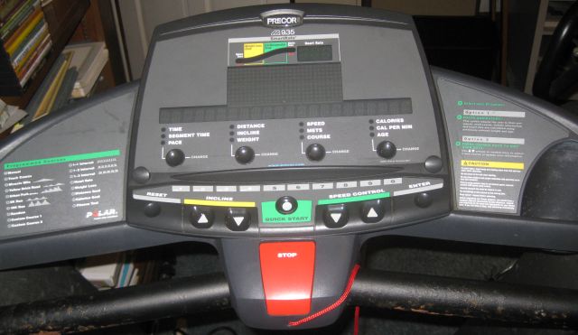
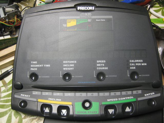
Around 2003 I bought a good quality Precor 9.35 treadmill, which M. and B. often used, and then it went on the blink – literally its various lights would blink but nothing happened. Some quick checks brought the conclusion that the circuit board was defective. Previously, when the wall oven and refrigerator failed, I located via the internet, outfits specialized in those circuit boards and sent them the board and received a working board a few days later (cost <$200). And the appliances worked and continue to work.
But wouldn’t it have been great to repair the board myself?
My first venture down this route was fixing the simple board on my scroll saw. It was frustrating, took a long time but I learned techniques along the way and succeeded. The treadmill board is more sophisticated.
Here is the underside of the circuit board – not much going on.
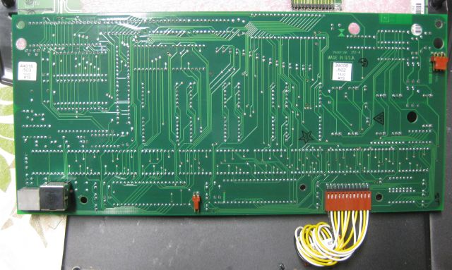
And here is the component side of the board. My starting point is to test the capacitors, cylindrical objects, of which there are 8.

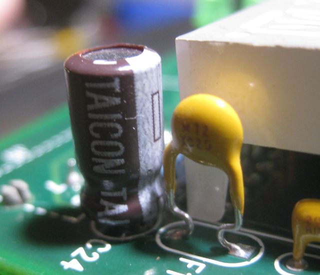
Here is a close up view of 3 capacitors.
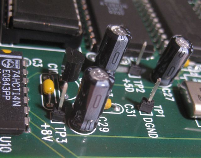
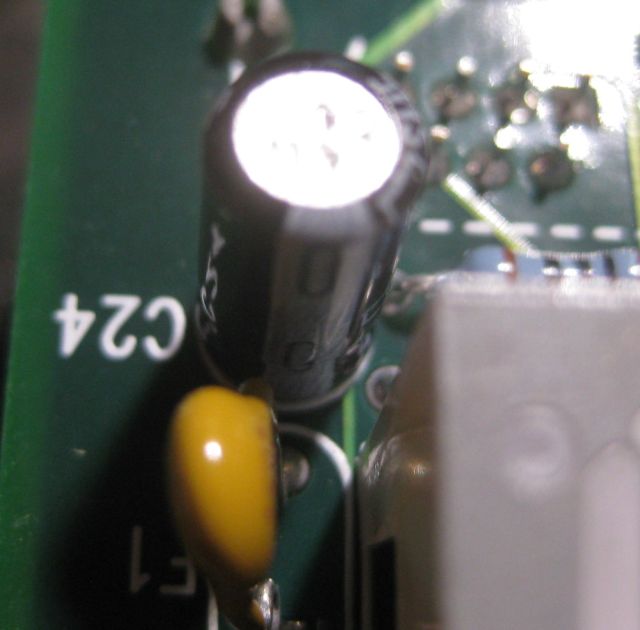
With my ESR meter I established that one capacitor was defective – 7 had an ESR of<0.31 and the defective cap had an ESR of 1. Here is the bad guy.
Diagnosis was quick. The actual replacement was difficult. Previously, to desolder a component I heated a soldered leg and with my other hand wiggled it free. But this was a multilayered board and it did not wiggle free. I figured lead free solder was used and raised the iron’s temperature. I was concerned too much heat would destroy the board. Touch and go. Eventually I was able to extricate the component but the holes, through which their legs had been inserted, promptly blocked up again with solder. With various diameter wires I was eventually able to clear the holes. Then I soldered a new component (same Farad rating, higher voltage, cost before shipping 15 cents), and it was done.
But was it fixed? That evening M. tested it and it worked – “significant event” she said!