
I have an old Sears Scroll Saw:
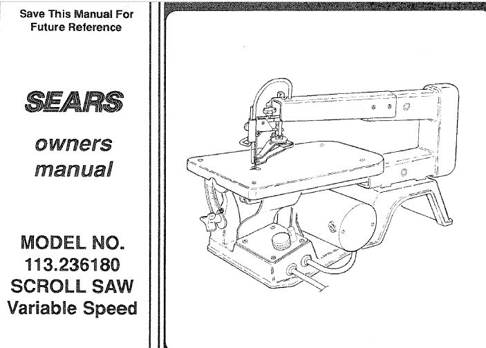
The manual is dated October ’92 so I must have purchased the scroll saw in the early 90’s. It worked fine though I did not use it much. Recently I had need for it but there was no response when I plugged it in.
Notice: If you are not competent with electricity do no attempt anything mentioned below – serious harm or death can result – instead seek professional assistance for your electrical problem.
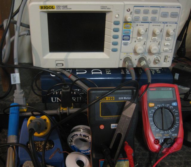
I removed the base plate to expose the circuit board and checked: a) was power reaching the circuit board (yes); b) was the on/off switch functioning (yes); c) was there a fuse which may have shorted (no); d) was power being output to the motor (no). Conclusion – the circuit board was receiving power, no fuse had shorted, the on off switch worked fine and no power was output to the motor which drives the saw. So the motor was fine and there was a problem with the circuit board.
Elsewhere on this website I describe how I shipped circuit boards of an oven and a refrigerator to a specialist firm for repair. Also how I have replaced capacitors of air conditioning units. And how I replaced the fuse of a Bose cd/radio. But I have never repaired a circuit board. So time for a new challenge.
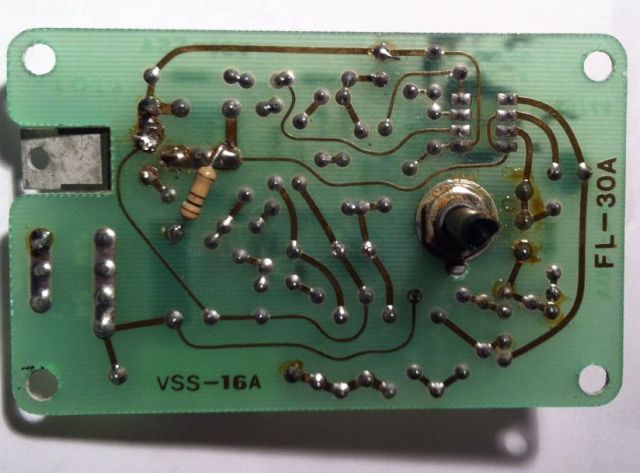
The beauty of old appliances is their circuit boards appear simple and are easier to work with than the modern stuff. The pcb (printed circuit board) of the Scroll Saw has relatively few components:
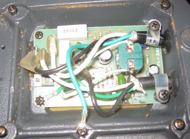
Here is a better pic with the connectors removed:
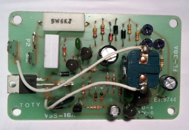
Some pcb’s have a numbering system for each of the components – not this one. The big green device on the right is the on/off switch. The 3 barrel looking devices with the silver tops are the capacitors – there usually is a problem with one of them. Then there are a number of resistors and diodes and several transistors (some covered in glue) and on the left, just above TOTY a thyristor with 3 legs. The rectangular horizontal white object at the top is a resistor and the rectangular vertical white object is a capacitor. Plus other items such as a varistor and pots.
You will notice on bottom right a number E1?9744. I hoped to find a schematic of this pcb on the web and fruitlessly googled this number which I thought was E119744 or some other combination. To no avail. Testing and replacing components is ok but I would much rather understand how the power supply actually works. I have a 1991 Radio Shack booklet on “Building Power Supplies” (compatible lineage) which was helpful explaining the principles of PWM etc. but even then I could not figure out how this particular pcb worked.
I thought the only way to test a capacitor is to unsolder and remove one of the legs from the circuit. I did this with the large cap (470 micron Farads) next to the switch, and it was fine, but what a pain for testing. Then I learned about ESR meters which can test caps seated on the pcb. Much easier. And guess what – the cap at the bottom (47 micron Farads) was defective. I placed an order for a replacement cap and got instead a 4.7 micron Farads cap. So I found an old pcb (one of my sons collected them) and unsoldered a 47 micron Farad cap and it tested fine and I installed it.
Here is an underside view of the pcb:
My next focus of interest was the thyristor the rectangular white object visible through the board cutout on the left of the picture. I surmised that the cut out was to allow the thyristor to be attached to a heat sink which would dissipate the heat generated during operation and therefore the non presence of a heat sink could have contributed to its failure. Design flaw?
From the topside view you can see the thyristor has 3 legs – a collector, emitter and base. No current flows unless voltage is applied to the base. When this occurs the thyristor should latch which means that when the voltage is removed from the base, the current continues to flow from collector to emitter. I unsoldered the thyristor and tested it and when base voltage was removed current stopped flowing from collector to emitter. It was defective. I ordered and installed a new thyristor (fortunately the defective component had sufficient information for identification).
I thought the pcb should work but it didn’t. I was stumped. I retested the components – all fine. Rather than mess with 120 VAC I connected the pcb to 24VAC – less chance of electrocution. And, unexpectedly instead of getting <1 VDC I suddenly got 16 VDC. I re-installed the pcb connected the power and, it didn’t work, back to <1VDC. A lot of head scratching and I concluded that one of my soldered joints must be faulty. Reconnected to 24VAC and gently pressed with a gloved finger each of the components – the voltmeter stayed below 1VDC. Then I pressed the thyristor and the meter showed >16VDC. Solution. On examination one of the legs was cold soldered so I resoldered it and got my >16VDS with the 24VAC supply. Reinstalled the pcb and connected to mains power and it works. The scroll saw is back in operation!